


Service hotline
+86 0755-83044319

release time:2023-03-31Author source:SlkorBrowse:18306
The junction temperature can be obtained from the case temperature.
Introduced in calculation method 1 or 2, the thermal resistance between the junction and the case is replaced by the thermal resistance between the junction and the environment: the calculation method of Rth(j-c). as follows.
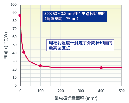
*Sacco uses a radiation thermometer to measure the temperature of the highest point on the marking surface. Please note that the measurement temperature can vary greatly depending on the measurement method.
**The power consumption is not fixed, and it is approximately calculated according to the average power consumption when time changes.
However, in particular, the value of Rth(j-c) varies greatly depending on the heat dissipation conditions of the mounted board and soldering, so please note that the measured value on our company's standard board may not be suitable for the customer's board. .
As an example, an example in which Rth(j-c) becomes smaller as the collector land area of the board becomes larger is shown. (In addition to the area, thickness, and material of the collector land, the material, size, and wiring size of the circuit board will also cause changes.)
For example, when the application time is 30ms, since Rth(j-a) is 20ºC/W, if a power of 3W is applied for 30ms at an ambient temperature of 25ºC, the junction temperature is
In this way, the value of Rth(j-c) tends to change depending on the board conditions, and it is difficult to measure the case temperature accurately, so it is not recommended as a method for estimating the junction temperature.
Junction temperature (or channel temperature) can be calculated from ambient temperature and power dissipation. According to the way of thinking about thermal resistance,
*Rth(j-a):The junction-to-ambient thermal resistance varies depending on the board on which it is mounted.
The value when mounted on our standard circuit board is shown as "resistance value of representative package".
The value of Rth(j-a) varies depending on each transistor, but it can be considered that the value is almost a close value if the package is the same.
**The power consumption is not fixed, and it is approximately calculated according to the average power consumption when time changes.
(For the calculation of the average power consumption, please refer to "How to judge whether a transistor can be used")
The figure below shows the relationship between power dissipation and junction temperature when Rth(j-a) is 250ºC/W and the ambient temperature is 25ºC.
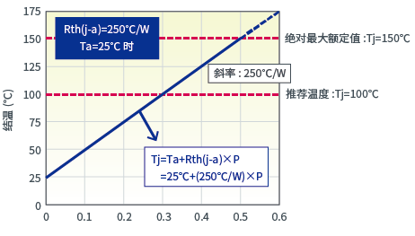
Junction temperature rises proportionally to power dissipation. The constant of proportionality at this time is Rth(j-a). Rth(j-a) is 250ºC/W,
So the junction temperature rises by 25ºC for every 0.1W increase in power dissipation.
The junction temperature is 150ºC when the power dissipation is 0.5W, so the power dissipation in this example cannot exceed 0.5W.
In addition, Rth(j-a) is also 250ºC/W, and changes in ambient temperature should be considered.
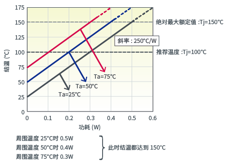
That is, even if the same power is applied, the junction temperature rises when the ambient temperature rises, so the power that can be applied becomes smaller.
Not only the thermal resistance, but also the ambient temperature will affect the maximum power dissipation. The power that can be applied is zero when the ambient temperature is 150°C, so
It can be seen that the maximum power consumption becomes smaller at the above ratio.
The power reduction curve below shows this relationship.
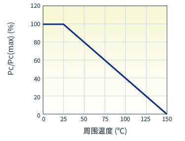
The derating rate of the power derating curve is expressed in percentage, so it can be applied to all packages.
For example, the maximum applied power of the MPT3 package at 25ºC is 0.5W, and the applicable power becomes smaller at the ratio of 0.8%/ºC.
At 50ºC, it becomes 80% of the original (20% reduction) or 0.4W, and at 100ºC it becomes 40% of the original (60% reduction) or 0.2W.
In "1. Depending on the ambient temperature (basic)", an example of continuous power application is considered.
Next, a temperature rise due to instantaneous power application is considered.
The temperature rise due to instantaneous power application is calculated using the transient thermal resistance.
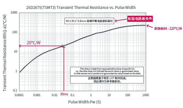
This graph represents the transient thermal resistance (transient thermal resistance). The horizontal axis is the pulse amplitude, and the vertical axis is the thermal resistance Rth(j-a).
It can be seen from the figure that as the application time becomes longer, the junction temperature rises, and after about 200 seconds, the heat is saturated and reaches a certain temperature.
For example, Rth(j-a) is 20ºC/W when the application time is 30ms, so if 3W power is applied for 30ms at an ambient temperature of 25ºC, the junction temperature is known to be:
When momentary power is applied once, the junction temperature can be obtained from this formula.To the product details page
The junction-case thermal resistance Rth(j-c) is originally a value used when a self-supporting device such as a TO220 package is fixed on a heat sink and used. In this case, the main heat dissipation path is between the case and heat sink, so the junction temperature can be correctly obtained by measuring the temperature of the case in this path. In particular, when it is assumed that a heat sink with ideal heat dissipation (infinite heat sink) is used, sometimes it is considered that the heat dissipation capacity is infinite, and the case temperature = atmospheric temperature, (display Tc=25ºC, etc.) case temperature = Calculated at 25ºC. (The thermal resistance of the infinite cooling plate: because Rth(c-a)=0, so Rth(j-a)=Rth(j-c).)
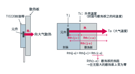
However, for surface-mount devices, heat dissipation from the circuit board under the device is the main heat dissipation path, so measuring the case temperature of this part is more difficult.
Since the heat dissipation ratio of the marked surface is small compared to the total heat dissipation, even if the temperature of the marked surface of the device is measured, it is not suitable as a value for estimating the junction temperature.
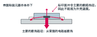
As for surface mount products, since most of them require to know the value of Rth(j-c), it is sometimes mounted on our standard circuit board to measure the temperature of the marked surface to provide the value of Rth(j-c). Rth(j-c) at this time is the value under the special condition of mounting on our company's standard circuit board. When mounting on a board different from our standard board, the ratio of heat dissipation from the marked surface changes, so the value of Rth(j-c) changes, and the junction temperature cannot be estimated.
This data is created based on the measurement of a specific LOT. Therefore, please use this data flexibly as a reference value.
(Not a guaranteed value and maximum and minimum values.)
Rth(j-a) will vary greatly depending on heat dissipation conditions and temperature measurement methods determined by mounting circuit boards and soldering,
So please use it flexibly as a reference value.
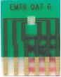
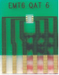
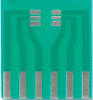
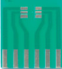
| Package | VMT3 | EMT3 | EMT5 | EMT6 | TUMT3 |
|---|---|---|---|---|---|
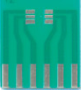
| Mounted circuit board |
|
|
|
|
|
|
FR4 board size (unit:mm) |
20×12×0.8 | 20×15×0.8 | 20×15×0.8 | 20×15×0.8 | 20×12×0.8 |
|
Rth(j-a)/ Rth(ch-a) |
833°C / W | 833°C / W | 1042°C / W | 1042°C / W | 313°C / W |
| Remark | - | - | When only 1 element works | When only 1 element works | - |
| Package | TUMT6 | UMT3 | UMT5 | UMT6 | SMT3 |
|---|---|---|---|---|---|
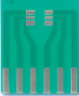
| Mounted circuit board |
|
|
|
|
|
|
FR4 board size (unit:mm) |
15×20×0.8 | 20×12×0.8 | 20×15×0.8 | 15×20×0.8 | 20×12×0.8 |
|
Rth(j-a)/ Rth(ch-a) |
313°C / W | 625°C / W | 1042°C / W | 1042°C / W | 625°C / W |
| Remark | When only 1 element works | - | When only 1 element works | When only 1 element works | - |
| Package | SMT5 | SMT6 | TSMT3 | TSMT5 | TSMT6 |
|---|---|---|---|---|---|
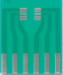
| Mounted circuit board |
|
|
|
|
|
|
FR4 board size (unit:mm) |
20×15×0.8 | 20×15×0.8 | 30×15×0.8 | 20×15×0.8 | 20×15×0.8 |
|
Rth(j-a)/ Rth(ch-a) |
625°C / W | 625°C / W | 250°C / W | 250°C / W | 250°C / W |
| Remark | When only 1 element works | When only 1 element works | - | When only 1 element works | When only 1 element works |
| Package | SOP8 | MPT3 | CPT3 | SST3 |

|
|---|---|---|---|---|---|
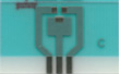
| Mounted circuit board |
|
|
|
|
|
|
FR4 board size (unit:mm) |
20×20×0.8 | 12×20×0.8 | 12×30×0.8 | 20×12×0.8 | |
|
Rth(j-a)/ Rth(ch-a) |
160°C / W | 250°C / W | 125°C / W | 625°C / W | |
| Remark | When only 1 element works | - | - | - |
TransistorTo the product details page


Site Map | 萨科微 | 金航标 | Slkor | Kinghelm
RU | FR | DE | IT | ES | PT | JA | KO | AR | TR | TH | MS | VI | MG | FA | ZH-TW | HR | BG | SD| GD | SN | SM | PS | LB | KY | KU | HAW | CO | AM | UZ | TG | SU | ST | ML | KK | NY | ZU | YO | TE | TA | SO| PA| NE | MN | MI | LA | LO | KM | KN
| JW | IG | HMN | HA | EO | CEB | BS | BN | UR | HT | KA | EU | AZ | HY | YI |MK | IS | BE | CY | GA | SW | SV | AF | FA | TR | TH | MT | HU | GL | ET | NL | DA | CS | FI | EL | HI | NO | PL | RO | CA | TL | IW | LV | ID | LT | SR | SQ | SL | UK
Copyright ©2015-2025 Shenzhen Slkor Micro Semicon Co., Ltd
