Service hotline
+86 0755-83044319

release time:2022-03-17Author source:SlkorBrowse:12677
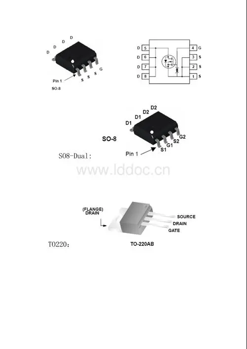
one. In fact, the FET triode is very good to judge: some are facing up from left to right: G, D, S, and some tubes are opposite: S, D, G. I repair the monitor, the motherboard, and the power supply from the above method. There is absolutely no problem. If you don't believe me, just disassemble the board and take a look. The layout of the FET on the circuit board and the detection of the VMOS high-power FET

two. 1 Distinguish each electrode and tube type
Use the multimeter R× 100 gear to measure the forward and reverse resistance values between any two pins of the field effect transistor. In one measurement, the resistance value of the two pins is hundreds of ohms. At this time, the pins connected to the two test leads are the source S and the drain D, and the other pin is the gate G.
Then use the multimeter R× 10k range to measure the forward and reverse resistance values between the two pins (drain D and source S). When normal, the forward resistance value is about 2kΩ, and the reverse resistance value is greater than 500kΩ.
When measuring the reverse resistance value, the pin connected to the red test lead does not move, and after the black test lead is separated from the connected pin, touch the grid G first, and then connect to the original pin to observe the change of the multimeter reading. If the multimeter reading changes from the original large resistance value to 0, the red test lead is connected to the source S, and the black test lead is connected to the drain D. Triggering the gate G with a black test pen is effective, indicating that the tube is an N-channel field effect transistor. If the reading of the multimeter is still a large value, connect the black test lead back to the original pin unchanged, and use the red test lead to touch the grid G and then connect it back to the original pin. If it is 0, then the black test lead is connected to the source S, and the red test lead is connected to the drain D. Triggering the gate G with a red pen is effective, indicating that the tube is a P-channel field effect transistor.
2. judge whether it is good or bad
Use the multimeter R×1k range or R×10k range to measure the forward and reverse resistance values between any two pins of the FET. In normal condition, the forward and reverse resistance values between the other pins (G and D, G and S) should be infinite except that the forward resistance value of the drain and the source is small. If the measured resistance value between two poles is close to 0Ω, it means that the tube has been broken down and damaged.
In addition, you can also use the method of triggering the gate (P-channel FET is triggered with a red test pen, N-channel FET is triggered with a black test pen) to judge whether the FET is damaged. If the trigger is valid (after triggering the gate G, the forward and reverse resistances between the D and S poles both become 0), it can be determined that the tube has good performance.
Three, 1 use 10K gear, there is a 15 volt battery inside. It can provide a conduction voltage.
2 Because the gate is equivalent to a capacitor, it cannot be connected to any pin,
No matter N tube or P tube, it is easy to find the grid, otherwise it is a bad tube.
3 Use the test lead to charge forward or reverse between the gate and the source, so that the drain and source can be turned on or off.
And because the charge on the gate can be maintained, the above two steps can be separated in succession, and it is not necessary to synchronize, which is convenient.
But to discharge, you need to short-circuit the pin or reverse charge.
4 There are anti-parallel diodes between the source and drain of most of them, which should be paid attention to and help to judge.
5 When most of them are facing themselves, the left gate is drained and the right source is drained.
The first three points above must be mastered, and the last two points can be used flexibly, and the pins can be judged quickly and divided into good and bad.
How to detect whether the MOS tube is burned out? The easiest steps
The detection of the MOS tube is mainly to judge the short circuit, leakage, amplification and open circuit of the MOS tube. Its operation steps are as follows:
①Connect the red pen to the source S of the MOS, and the black pen to the drain of the MOS tube. A good pointer should indicate infinity. If there is a resistance value that is not tested, the MOS tube has leakage.
②Use a 100KΩ-200KΩ resistor to connect the gate and the source, then connect the red pen to the source S of the MOS, and the black pen to the drain of the MOS tube. At this time, the value indicated by the needle is generally 0, at this time, the lower charge charges the gate of the MOS tube through this resistor, generating a gate electric field. Due to the electric field, the conductive channel causes the drain and source to conduct, so the multimeter pointer is deflected, the deflection angle is large, and the discharge Sex is better.
③Remove the resistance connecting the gate and the source, and the red and black pens of the multimeter remain unchanged. If the needle gradually returns to high resistance or infinity after the resistance is removed, the MOS tube leaks electricity, and it remains intact.
④ Finally, connect the gate and source of the MOS tube with a wire. If the pointer returns to infinity immediately, the MOS tube is intact, otherwise the MOS tube has been burned out.


Site Map | 萨科微 | 金航标 | Slkor | Kinghelm
RU | FR | DE | IT | ES | PT | JA | KO | AR | TR | TH | MS | VI | MG | FA | ZH-TW | HR | BG | SD| GD | SN | SM | PS | LB | KY | KU | HAW | CO | AM | UZ | TG | SU | ST | ML | KK | NY | ZU | YO | TE | TA | SO| PA| NE | MN | MI | LA | LO | KM | KN
| JW | IG | HMN | HA | EO | CEB | BS | BN | UR | HT | KA | EU | AZ | HY | YI |MK | IS | BE | CY | GA | SW | SV | AF | FA | TR | TH | MT | HU | GL | ET | NL | DA | CS | FI | EL | HI | NO | PL | RO | CA | TL | IW | LV | ID | LT | SR | SQ | SL | UK
Copyright ©2015-2025 Shenzhen Slkor Micro Semicon Co., Ltd
