Service hotline
+86 0755-83044319

release time:2022-03-17Author source:SlkorBrowse:10286
The relationship between medical equipment and modern medical diagnosis and treatment is increasingly close. Any medical equipment can't be separated from a safe and stable power supply, and most of them are switching power supplies. Whether a medical device can exert its maximum efficiency is not only directly related to the technical performance of the machine itself, but also related to the quality of the power supply. The quality of power supply will directly affect the stability and reliability of medical equipment. Products with substandard power supply may lead to major medical equipment accidents and huge economic losses.
Safety-isolation is an important difference between common commercial power supply and medical power supply. General medical equipment is divided into two categories based on power supply, as shown in Figure 1 and Figure 2. Class I medical equipment (metal case) and Class II medical equipment (plastic case). Except for some experimental and analytical instruments, most medical equipment is installed near the treatment point, which is close to people, and the shell is often touched. There are all kinds of strong and weak components in medical equipment. If there is a problem in isolation between strong and weak components or insulation of shell materials, it will be very dangerous, so isolation design is needed.
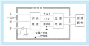
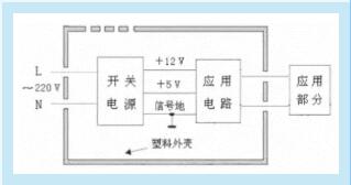
Figure 1 Electrical structure of class I medical equipment Figure 2 Electrical structure of class II medical equipment
Different modules in the equipment need different levels of isolation:functional isolation, basic isolation, double isolation and enhanced isolation.
Functional isolation refers to the functional application isolation of signals or power supplies between voltage systems, only for cross-functional modules;
Isolation is basically functional isolation+electric shock protection;
Double isolation adopts a system with basic isolation (basic level of protection against electric shock), and an auxiliary insulation layer is added between the electrical components and the end user to strengthen physical protection, so as to reduce the possibility of electric shock when basic isolation fails;
The isolation effect of enhanced isolation is related to double isolation, but only a single shell is needed. It is a basic isolation decoration with enhanced isolation characteristics, which can make use of the physical isolation between printed circuit board layout, core wires, windings and parts pins, etc., and at the same time meet the requirements of safe creepage distance and electrical clearance distance (i.e. the physical distance between two voltage systems).
Therefore, the design of enhanced isolation has double isolation, but only one test point is needed.Double isolation and enhanced isolation are generally applicable to products that use AC plugs without grounding pins to connect the power supply, such as portable medical equipment (for example, the infusion pump and its plug in Figure 3).
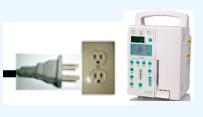
Figure 3
As shown in Figure 1 and Figure 2, according to the safety standard of medical power supply, the isolation requirements of equipment for patient protection are as follows. (1)L, N←→ application part: double or reinforced insulation, dielectric strength AC 4000 V, electrical clearance 5 mm, creepage distance 8mm; (2)L, N←→ metal shell: basic insulation, dielectric strength AC 1500 V, electrical clearance 2.5 mm, creepage distance 4 mm
To sum up, "functional isolation" and "basic isolation" (i.e. class I isolation) electrically isolate one voltage rail from another, while "double isolation" and "enhanced isolation" provide two solutions in different situations for the same design goal (i.e. class II isolation). Class I products and class II products should choose two kinds of isolation methods.The internal structure of medical switching power supply is divided according to the standard, and the dielectric strength, electrical clearance and creepage distance of different parts need to be designed according to the requirements.In terms of safety testing, the power supply of general medical equipment must be certified by UL60601-1, C-UL, EN60601-1, etc. The input terminal must have an isolation voltage of more than 4,000V, and the floor drain current should be low, which meets the requirements of safety creepage distance. However, double insulation is required for the high-voltage part, especially for the part likely to contact with the equipment shell, the insulation and isolation design should be strengthened.
Fig. 4 and fig. 5 show the electrical structures of two types of power supplies. According to the medical power supply standard (GB 9706.1-2007 standard), the isolation parameters of the medical power supplies with the structures shown in fig. 4 and fig. 5 are E1-dielectric strength AC 1500 V, electrical clearance 2.5 mm and creepage distance 4 mm;; E3— dielectric strength AC 4 000 V, electrical clearance 5 mm, creepage distance 8 mm;; E4— dielectric strength AC 500 V. Relative: C1-Y2 capacitor, C2-X2 capacitor, C3-equivalent to double Y1 series capacitor.
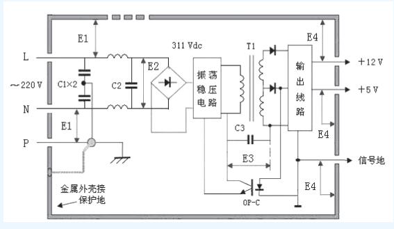
Fig. 4 electrical structure of class I power supply
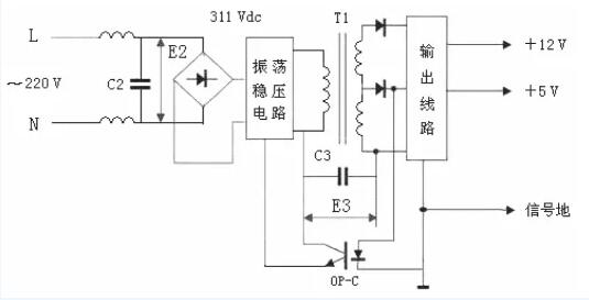
Figure 5 Electrical Structure of Class II Power Supply
These parameters of isolation requirements require designers to ensure that devices with appropriate margins are selected from the beginning of device selection.In addition, in terms of power supply types, domestic medical equipment is mostly powered by 220V mains. Due to the power supply requirements of various types of medical equipment, centralized power supply structure is the most widely used one at present. That is, a centralized power converter generates the required output voltages of various voltage levels.
Because of its low cost, high efficiency, adjustable output voltage, low output noise and fast dynamic response, it is very suitable for medical equipment, and it is the most widely used power supply mode for medical equipment at present. That is, as shown in fig. 6, the switching power supply of medical equipment involves AC/DC and DC/DC.The input of AC/DC converter of primary power supply is 50/60Hz and 220V alternating current, which must be rectified and filtered. Large filtering electrolytic capacitor is indispensable, and the AC input must be added with EMC filter and devices using safety standards.The DC/DC converter of secondary power supply is used for power conversion, which is the core part of switching power supply.
In addition, there are circuits such as start-up, overcurrent and overvoltage protection, noise filtering, etc. The sampling circuit detects the change of the output voltage and compares it with the reference voltage. The error voltage is amplified and pulse width modulated (PWM) circuit, and then the duty cycle of the power device is controlled by the driving circuit, so as to adjust the output voltage. The basic structure is shown in Figure 6.
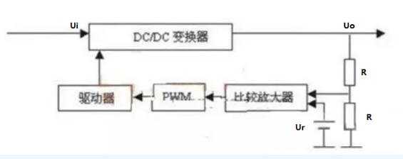
Figure 6 Basic structure of medical equipment switch
The input circuit generally includes switch, fuse, AC anti-interference circuit and soft start circuit.
Soft start circuit is one of the protection circuits of switching power supply. Most of the input circuits of switching power supply are designed by rectifying and capacitor filtering circuit. Because the initial voltage on the capacitor is 0, a large instantaneous surge current will be formed. For this reason, the switching power supply of medical equipment is generally equipped with a soft start circuit to prevent surge current in the input circuit.
Common soft-start circuits include thermistor anti-surge current circuit, SCR-R circuit, circuit composed of relay and resistor, circuit using timing trigger and current limiting resistor, and circuit composed of photo-coupled thyristor and bidirectional thyristor triggered by zero crossing.
One of the circuits to realize the zero-crossing trigger is shown in Figure 7. Two optocouplers are used for AC input, and two optocouplers are reversely connected in parallel. In the positive and negative half cycles of the commercial power, the two optocouplers are turned on in turn. When the commercial power is not at the zero-crossing point, only one optocoupler is turned on, and the low level is output at this time. When the commercial power turns to the zero-crossing, both optocouplers are not turned on. At this time, due to the action of R3, the pin outputs a high level, thus obtaining a pulse signal with a fixed period at the output end.
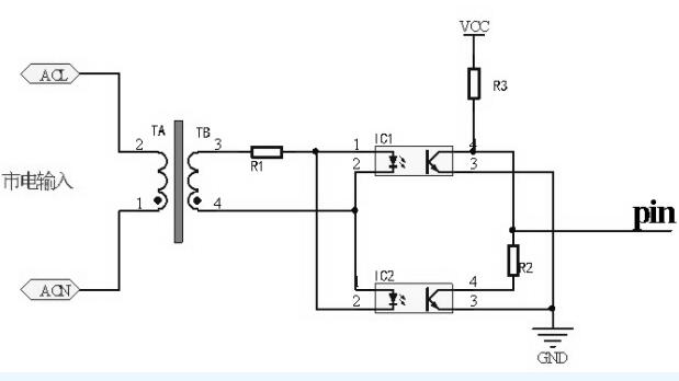
Fig. 7 the circuit of zero-crossing trigger with optocoupler
Due to unidirectional signal transmission, the input end and the output end are completely electrically isolated, with strong anti-interference ability, long service life and high transmission efficiency. Optocouplers are widely used in signal isolation, switching circuits, pulse amplification, solid state relay (SSR) and other circuits.In the application of AC load, optocoupler and bidirectional thyristor form an isolation circuit with strong anti-interference ability.Optocouplers can isolate different circuit modules in the switching power supply.For circuit voltage stabilization, linear optocoupler can be used in pulse width modulation (PWM) circuit to form optocoupler feedback circuit, and the duty ratio can be changed by adjusting the current at the control terminal to achieve the purpose of precise voltage stabilization.Because of its wide application in medical products, the quality of optocoupler has a great influence on medical switching power supply. In order to avoid the circuit failure caused by the degradation of optocoupler performance and ensure the stability and safety of medical products, reliable optocoupler products must be selected.In addition, in order to choose or build a good power supply system for medical equipment, we must pay attention to improving the electromagnetic compatibility and anti-electromagnetic interference ability of the power supply. Mainly from the PCB design and layout, electromagnetic shielding, testing and certification. For PCB design, the main point is power isolation, and the core is the choice of optocoupler. From these aspects, we can expand and choose the appropriate optocoupler. See this article for how to choose it.
Disclaimer: This article is reproduced from "Dashengtang Electronics". This article only represents the author's personal views, and does not represent the views of Sakewei and the industry. It is only for reprinting and sharing to support the protection of intellectual property rights. Please indicate the original source and author when reprinting. If there is any infringement, please contact us to delete it.
Company Tel: +86-0755-83044319
Fax/fax:+86-0755-83975897
Email: 1615456225@qq.com
QQ: 3518641314 Manager Li
QQ: 332496225 Manager Qiu
Address: Room 809, Block C, Zhantao Technology Building, No.1079 Minzhi Avenue, Longhua New District, Shenzhen


Site Map | 萨科微 | 金航标 | Slkor | Kinghelm
RU | FR | DE | IT | ES | PT | JA | KO | AR | TR | TH | MS | VI | MG | FA | ZH-TW | HR | BG | SD| GD | SN | SM | PS | LB | KY | KU | HAW | CO | AM | UZ | TG | SU | ST | ML | KK | NY | ZU | YO | TE | TA | SO| PA| NE | MN | MI | LA | LO | KM | KN
| JW | IG | HMN | HA | EO | CEB | BS | BN | UR | HT | KA | EU | AZ | HY | YI |MK | IS | BE | CY | GA | SW | SV | AF | FA | TR | TH | MT | HU | GL | ET | NL | DA | CS | FI | EL | HI | NO | PL | RO | CA | TL | IW | LV | ID | LT | SR | SQ | SL | UK
Copyright ©2015-2025 Shenzhen Slkor Micro Semicon Co., Ltd
