Service hotline
+86 0755-83044319
release time:2022-03-17Author source:SlkorBrowse:13956
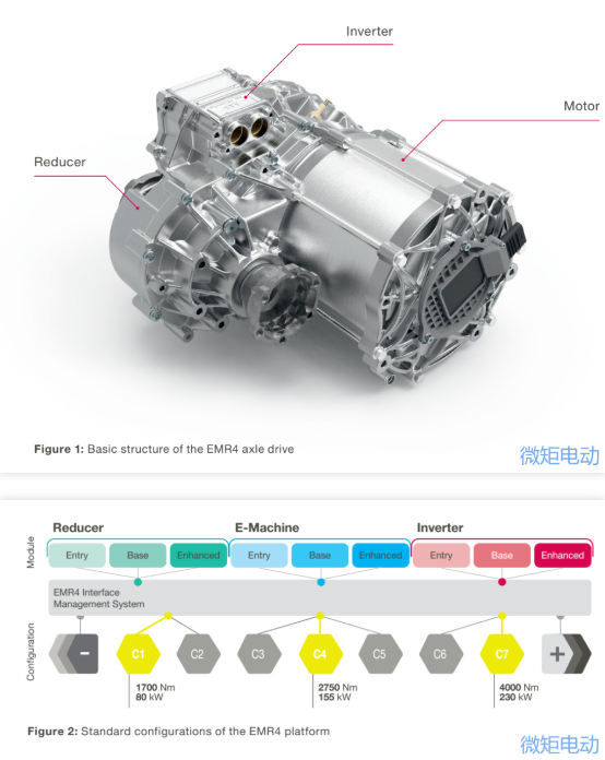 With this basic structure, it is possible to connect two components that need the greatest variability in different designs, and the modification requirements of the reducer gearbox can be realized within the size of the casing. This inline arrangement forms the basis of key architectural features of EMR4. The standard configuration planned during the development process (for vehicles in sections A to J2, that is, the vehicle weight class is from 1,800kg to 2,800kg) can be covered by three dimensions of motor length: 60mm (entry level), 90mm (basic level) or 105mm (enhanced level), as shown in Figure 2. According to the design, the newly developed EMR4 drive system provides 80kW and maximum 230kW power (10 seconds). The torque range of the drive system is from 1,700Nm to 4,000Nm(10 seconds), and the scalability is obvious in the weight of the module. According to the power demand of the drive, its weight is between 45kg and 80kg. According to the previous research results, compared with EMR3, EMR4 drive system can achieve an efficiency advantage of 5.6% in WLTP, which will have a significant impact on vehicle mileage. These values are obtained by systematic optimization of several central effect chains in the drive system. The potential for improvement has been realized through many detailed measures here. Compared with the optimized EMR3, the efficiency of EMR4 has increased considerably, the power density has increased by more than 20%, but the cost has been further reduced. Although EMR4 uses high-quality materials in many places, the technical advantages of materials make it possible to save more costs in other fields and optimize the costs.
2.1 Architecture and motor The diameter of the PSM motor (its shell diameter) has been designed for the integrated EMR4 fixation. The stator outer diameter of R4 platform motor is 208mm, which is slightly larger than 20mm compared with EMR4 motor. However, the design measures to improve the performance of the motor have reduced the axial length of EMR4 motor by nearly half compared with the current axial drive (90mm instead of 175mm). Now the stator has at least four layers per groove (instead of two layers in EMR3). The number of floors (such as 4-8 floors) selected according to the specific situation in the future is determined strictly according to the required cost requirements and performance level or voltage. The balance between minimizing the cost and maximizing the potential of moving parts is an important factor to consider.
2.2 Architecture and power electronic controller The inverter of platform R4 is the fourth generation high-voltage power electronic product based on Vitesco Technologies (EPF4). For the power range of EMR4 platform, the highly integrated EPF4 inverter can provide three power levels: 290A (entry level), 550A (basic level) and 820A (enhanced level). The version of Entry provides a cost-effective solution with an output of up to 80kW(10s) and a torque of 1700Nm(10s). The version is basically suitable for a wide range of applications, with a power output of up to 135/165kW(10s) and a torque of 2,500/3,000 Nm(10s). Enhanced design for output at 2800Nm and 4000Nm, up to 230kW power. However, in principle, all inverter variants can be combined with each motor power variant and each required reducer. This needs to meet the special requirements (e.g., logistics vehicles) different from standard mass passenger cars. The inverter size is only 270. × 221 × 126mm,It is a very compact design.
2.3 And frame reducer According to the torque of the motor, the platform includes three versions of reducers configured as< 2,000 Nm(“entry level”)、< 3,000 Nm(“Basic level”)或< 4,000 Nm(“Enhanced level”)。 Estimated reduction ratio between i = 9.3 and i = 11.64. Compared with the previous generation, this reduction ratio has been expanded, making it possible to make the best use of the higher peak speed of the motor. In the reducer, this high reduction ratio measure can significantly save the cost of the motor, and provide an opportunity to reduce the cost in terms of the cost of higher quality materials. The reducer is designed with an input speed of 16000 rpm and a motor torque input of 255 Nm. The reducer provides the output of shaft torque up to 3000 Nm. The maximum allowable shaft speed is 1720 rpm. Electric parking can optionally be integrated into the reducer.
3. Optimization of factors affecting efficiency Worldwide, the trend of further improving the efficiency of electric vehicles is obvious. Mileage and battery size/cost considerations, as well as legal requirements aimed at controlling air pollution and mitigating climate change, all contribute to this. In addition, the further improvement of electric drive efficiency also increases the attractiveness of automobiles, because the resulting system cost is reduced. Wh/km in WLTP is used to measure energy consumption. Many single factors determine the efficiency of a car. Although most of them are caused by the whole vehicle, the power system also has considerable influence.Many single factors determine the efficiency of a car. Although most of them are caused by the whole vehicle, the power system also has considerable influence.
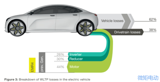
Fig. 3 Taking the integrated drive system as an example, it illustrates the influence of the power system and its specific losses on the efficiency of the whole vehicle. Generally speaking, about one-third of the losses are caused by driving, and about two-thirds are caused by the whole vehicle. EMR4 has made further progress in power electronic inverter, motor and reducer, and improved the overall efficiency of the vehicle: compared with the previous generation, the efficiency of EMR4 is much higher, and the average total energy consumption of each D-class vehicle can be reduced by 5.6% in WLTP.
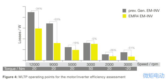
 3.1 And the efficiency of the motor and inverter is improved. In the Active parts of EMR4 platform, a laminated iron core made of very thin and high-strength silicon steel sheets is used to achieve higher motor speed with less materials. At present, the maximum speed is 16,000 rpm (EMR 3: 14,000 rpm). By increasing the gear ratio, the motor torque can be reduced, thus saving motor materials. In addition, the continuous power of EMR4 motor has been greatly improved. As the loss is greatly reduced and the cooling structure is optimized, the motor can continuously output 40-80kW at the highest speed. Due to the short length and compact design of the motor, the heat dissipation is more effective, because there is a shorter heat dissipation path from the hot spot in the center of the motor to its edge. The increased gear reduction ratio (see Section 2.3) means that lower motor torque is required under the same shaft torque. Combined with the new rotor sheet metal cutting and the increase of magnetic resistance, the weight of magnetic steel is significantly reduced, the power remains unchanged and the efficiency is improved. The working voltage of EPF4 inverter is 210V to 470v, and the PWM switching frequency is 2 to 12kHz. According to the different working points, the field oriented control (FOC) algorithm is applied in sections, such as traditional space vector pulse width modulation (= SVPWM at low speed to enable higher current), synchronous PWM (=SynchPWM at medium speed range), discontinuous PWM (= GDPWM at medium speed range) and bidirectional flux modulation (=FBM at high speed range). The rotor position sensor at the front end of the motor provides the rotor position signal. Figure 4 shows the reference operating points used to evaluate the losses of motor and inverter in the simulation process. The higher efficiency gain, especially when rotating at high speed, is precisely because the thinner motor silicon steel sheet can reduce the iron loss by increasing the number of laminated layers.
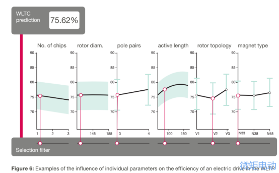
 4. Implementation method of EMR4 platform The application range of integrated electric drive system is expanding day by day. Only with high scalability in performance, efficiency, cost, size and weight, can it meet the diversified requirements of the market. Scalability ultimately means that the related main components can be combined to meet the requirements according to the application. Considering the large number of parameters that define the required performance characteristics of the drive system and the complex interaction between them, it is very challenging in design to thoroughly implement the details. For example, during the development of EMR4 platform, we conducted extensive sensitivity analysis to determine the influence of a single parameter in WLTP on the efficiency of electric drive system, as shown in Figure 6.
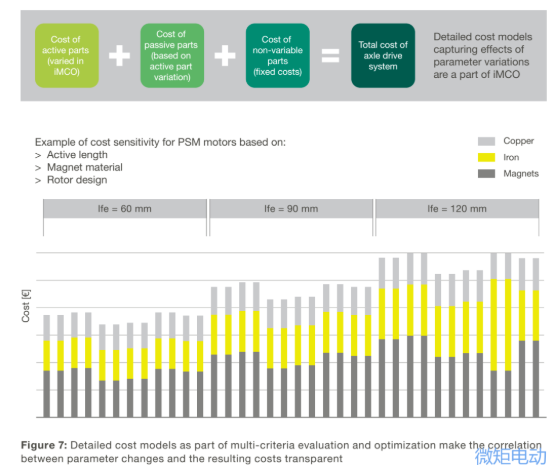
 In order to achieve the optimal weight of expected performance characteristics and related costs, the developers used the special tool iMCO in this multi-standard development stage, as shown in Figure 7.
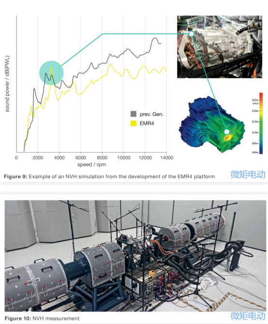
 5. And internal and external interfaces. As mentioned earlier, when designing the integrated drive system, the complexity of the separately designed electric drive has been completely simplified from the perspective of the whole vehicle, and the complexity has been transferred to the inside of the drive system. Here, the transfer of complexity can also be proved from many interfaces inside and outside the drive system. Figure 8 shows the internal interfaces between various functions in the drive system, highlighted in gray, and the external interfaces of the whole vehicle are shown in green circles. In order to realize the full expansibility of the pre-verification EMR4 platform components, all major components, namely, inverter (three versions), reducer (three variants), rotor and stator (three lengths each), motor casing (three lengths) and bearing plate (two versions of "covers") have clear definitions about internal and external interfaces. This makes it possible to combine different component designs with a unified interface. Noise and electromagnetic radiation are also the key indexes of electric drive system. In order to minimize the influence of structural noise on vehicle body vibration in electric drive, a lot of optimization work has been done on the acoustic quality (noise, vibration, harshness, NVH) of the drive system under all operating conditions, as shown in Figures 9 and 10. On EMR4 platform, the simulation results have been successfully tested based on A-sample. This simulation technology can also be used to optimize the shape of the bracket and avoid the excitation resonance related to the structural design of the vehicle.
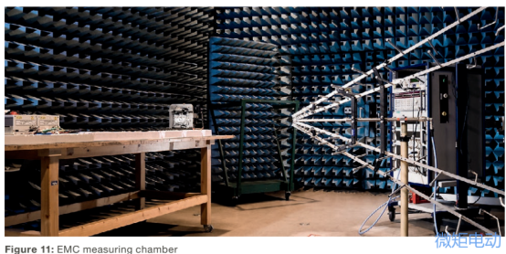
 The electromagnetic compatibility of EMR4 platform conforms to CISPR25-2016 Class 3 standard, as shown in Figure 11.
 6. summarize The development of the R4 platform has absorbed the industrialization experience of three generations of electric drive systems: by the beginning of 2021, EMR4 alone has delivered more than 150,000 units to customers. The efficiency and performance of the EMR4 have been significantly improved at a lower cost, even compared with the optimized EMR3 drive system. Especially, the high scalability of the new platform makes EMR4 drive system have a high cost-effective application prospect in various different models. At present, the expandable output power of the EMR4 platform is between 80kW and 230kW, and the mass is only between 45 kg and 80 kg. The high power density supports the transition of a large number of models to electrification. In order to cover the performance requirements above or below the specified current range, the development of portfolio expansion will begin in 2021. Through the cost optimization of the system, EMR4 platform helps the purchase cost of electric vehicles to approach the standard of internal combustion engine vehicles in the past. As the efficiency of EMR4 drive system is further improved, the cost of battery is also reduced. The EMR4 platform represents customized off-the-shelf solutions, and always focuses on standardization and modularization of products. Under the system restriction, customer-specific differentiation is formed through integration and system expertise. This method creates a balance between cost optimization and personalization, supplemented by years of production experience and quality control. Based on this strategy, Vitesco Technologies is actively cooperating with customers and suppliers to promote the growth of electric travel.
Thoughts on platform products I believe many companies have analyzed how to platform the three-in-one electric drive system, and Vitesco EMR4's platform thinking has given us a lot of enlightenment: ① Axial integration is selected as the integration form, so that the motor and inverter are decoupled, and the motor with larger outer diameter is selected. The expansion of power is adjusted by the core stack thickness, and the core punching can be completely platformized; ② From the point of view of inverter current specification, IGBT module should be HPD package, and different current specifications are formed by different chip numbers and combinations of heat dissipation boards;
6. summarize The development of the R4 platform has absorbed the industrialization experience of three generations of electric drive systems: by the beginning of 2021, EMR4 alone has delivered more than 150,000 units to customers. The efficiency and performance of the EMR4 have been significantly improved at a lower cost, even compared with the optimized EMR3 drive system. Especially, the high scalability of the new platform makes EMR4 drive system have a high cost-effective application prospect in various different models. At present, the expandable output power of the EMR4 platform is between 80kW and 230kW, and the mass is only between 45 kg and 80 kg. The high power density supports the transition of a large number of models to electrification. In order to cover the performance requirements above or below the specified current range, the development of portfolio expansion will begin in 2021. Through the cost optimization of the system, EMR4 platform helps the purchase cost of electric vehicles to approach the standard of internal combustion engine vehicles in the past. As the efficiency of EMR4 drive system is further improved, the cost of battery is also reduced. The EMR4 platform represents customized off-the-shelf solutions, and always focuses on standardization and modularization of products. Under the system restriction, customer-specific differentiation is formed through integration and system expertise. This method creates a balance between cost optimization and personalization, supplemented by years of production experience and quality control. Based on this strategy, Vitesco Technologies is actively cooperating with customers and suppliers to promote the growth of electric travel.
Thoughts on platform products I believe many companies have analyzed how to platform the three-in-one electric drive system, and Vitesco EMR4's platform thinking has given us a lot of enlightenment: ① Axial integration is selected as the integration form, so that the motor and inverter are decoupled, and the motor with larger outer diameter is selected. The expansion of power is adjusted by the core stack thickness, and the core punching can be completely platformized; ② From the point of view of inverter current specification, IGBT module should be HPD package, and different current specifications are formed by different chip numbers and combinations of heat dissipation boards;③ The reducer selects a large reduction ratio, which can reduce the motor torque. Reducing the torque can directly reduce the amount of motor materials and reduce the motor cost. IMCO, a special tool, is mentioned in multi-standard optimization based on motor efficiency, performance and cost, which can also be referred to.
Disclaimer: This article is reproduced from "Technical Information of New Energy Vehicles". This article only represents the author's personal views, and does not represent the views of Sacco Micro and the industry. It is only for reprinting and sharing to support the protection of intellectual property rights. Please indicate the original source and author when reprinting. If there is any infringement, please contact us to delete it.
Company telephone:+86-0755-83044319
facsimile/FAX:+86-0755-83975897
mailbox:1615456225@qq.com
QQ:3518641314
QQ:332496225 Manager Qiu
Address: Room 809, Block C, Zhantao Technology Building, No.1079 Minzhi Avenue, Longhua New District, Shenzhen


Site Map | 萨科微 | 金航标 | Slkor | Kinghelm
RU | FR | DE | IT | ES | PT | JA | KO | AR | TR | TH | MS | VI | MG | FA | ZH-TW | HR | BG | SD| GD | SN | SM | PS | LB | KY | KU | HAW | CO | AM | UZ | TG | SU | ST | ML | KK | NY | ZU | YO | TE | TA | SO| PA| NE | MN | MI | LA | LO | KM | KN
| JW | IG | HMN | HA | EO | CEB | BS | BN | UR | HT | KA | EU | AZ | HY | YI |MK | IS | BE | CY | GA | SW | SV | AF | FA | TR | TH | MT | HU | GL | ET | NL | DA | CS | FI | EL | HI | NO | PL | RO | CA | TL | IW | LV | ID | LT | SR | SQ | SL | UK
Copyright ©2015-2025 Shenzhen Slkor Micro Semicon Co., Ltd