Service hotline
+86 0755-83044319

release time:2022-03-17Author source:SlkorBrowse:10943
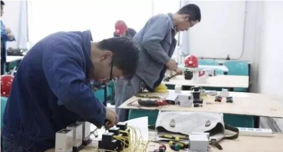
The installation and debugging of PLC control system involves all kinds of work, and can only be carried out in sequence, with one link closely linked to another. Any carelessness will lead to debugging failure, which will not only delay the construction period, but even damage the equipment. This paper introduces the technical experience of installation and debugging of PLC control system summed up in the field practice, and puts forward some suggestions and solutions to the problems related to installation and debugging that often occur in the field.
Reasonable arrangement of system installation and debugging procedures is the key to ensure efficient and high-quality completion of installation and debugging tasks.
1、Pre-technical preparation
The more adequate the technical preparation before the installation and debugging of the system, the smoother the installation and debugging will be. The preliminary technical preparations include the following contents:
(1)Be familiar with the technical data and original data of PC, deeply understand its performance, functions and various operation requirements, and formulate operation procedures.
(2) Have a thorough understanding of the design data, the process flow of the system, especially the control requirements of the process for each production equipment. On this basis, draw the process flow by subsystem. Process interlocking diagram, system function diagram, system operation logic block diagram, which will be helpful for a deep understanding of system operation logic, are important links of early technical preparation.
(3) Be familiar with the performance, design and installation of each process equipment, especially the control and power wiring diagram of each equipment, and compare it with the physical objects, so as to find errors and correct them in time.
(4) On the basis of comprehensive understanding of the design scheme and PC technical data, list the PC input and output point number table (including the list of internal coils, I/O location, corresponding equipment and functions of each I/O point).
(5) Read the program provided by the design, and draw the sequence diagram for some input and output points with complex logic. Some logic errors in the design can be found when drawing the sequence diagram.
(6) Compile the debugging scheme of molecular system, and then synthesize it into the whole system debugging scheme on the basis of collective discussion.
2、PLC commodity inspection
Commodity inspection shall be conducted jointly by Party A and Party B, and the models, quantities and specifications of equipment, spare parts, technical data, accessories, etc. shall be confirmed, and whether their performance is in good condition shall be verified in laboratory and on-site debugging. As a result of the commodity inspection, both parties shall sign the exchange list.
3、Laboratory debugging
(1)PLC laboratory installation and opening make metal bracket, fix the input and output modules of each workstation on it, connect each station with the host, programmer, printer, etc. by coaxial cable according to the installation summary, check that the wiring is correct, and after the power supply level is consistent with the PLC voltage selection, send power according to the startup procedure, load it into the system configuration belt, confirm the system configuration, load the programmer loading belt, programming belt, etc., and open the system according to the operating procedures. At this time, all items can be carried out.
(2) Type the working procedure.
(3) Simulate I/O input and output, and check the modified program. The purpose of this step is to verify the correctness of the input working program, whether the interlocking relationship of process equipment expressed by the logic of this program is consistent with the design process control requirements, and whether the program is smooth. If it doesn't match or can't run the whole process, the program is wrong and should be modified. In this process, the understanding of the program will gradually deepen, making preparations for on-site debugging. At the same time, unreasonable and imperfect parts of the program can be found for further optimization.
There are two debugging methods:
① Simulation method: make a debugging board according to the design, simulate the input node with toggle switch, simulate the relay and contactor of production process equipment with small relay, and its auxiliary contact simulates the return signal node when the equipment is running. Its advantage is that it has the authenticity of simulation, and it can reflect whether the logic misoperation will occur when the field mechanical contacts with different switching speeds and the electronic contacts in PLC are connected with each other. Its disadvantage is that it needs to increase the debugging cost and part of the debugging workload.
② Forcing method: Using the forcing function of PLC, make the mechanical contacts (switches) involved in the program "on" and "off" by forcing the program to run. Its advantages are small debugging workload, simplicity and no additional cost. The disadvantage is that the logic verification is not comprehensive, and artificially forcing the analog field nodes to be "on" or "off" will cause the program running to be discontinuous and can only be carried out in sections.According to our experience of on-site debugging, some important on-site nodes are simulated, and others are forced, so that their strengths complement each other. In the logic verification stage, it is important to fill in the commissioning log daily, including commissioning personnel, time, commissioning contents, modification records, fault treatment, handover and acceptance signature, so as to establish the commissioning responsibility system and leave the first-hand information of commissioning. The modified part of the design procedure should be indicated on the design drawing, and the opinions of the designer should be sought in time, so as to accurately reflect the design requirements.
4、On-site installation and inspection of PLC
After the laboratory debugging is completed, move the equipment to the site for installation when the conditions are ripe. The installation shall meet the requirements, the plug-in shall be inserted firmly and fastened with bolts; Communication cables shall be of the same model and cannot be mixed. When necessary, instruments shall be used to check the attenuation of line signals, and the attenuation value shall not exceed the indicators put forward in the technical data. Measure the ground insulation resistance of the host, I/O cabinet, connecting cable, etc. Measure the grounding resistance of the system dedicated grounding; Check the power supply, etc., and make records. After all items are confirmed to meet the requirements, power on the machine.
5、Inspection and adjustment of field process equipment wiring, I/O contacts and signals
Check and confirm the correctness of the wiring of the control loop and main loop of each process equipment on site, and conduct the monomer test run in manual mode; Check all the input points into the PLC system (including transfer switches, buttons, contacts of relays and contactors, limit switches, position debugging switches of instruments, etc.) and their connections with the PLC input module, and operate them repeatedly to confirm their correctness; Check all relays, contactor coils and other actuators that receive PLC output and their connections with output modules to confirm their correctness; Measure and record its circuit resistance and ground insulation resistance. If necessary, supply power to the output circuit according to the power supply voltage level of the output node to ensure that the output circuit is not short-circuited. Otherwise, when the output point sends power to the output circuit, the module will be burned out due to short circuit.
Generally speaking, large and medium-sized PLC can also receive and output analog signals if it is equipped with analog input and output modules. In this case, it is necessary to check the primary detection or transmission elements that send analog input signals to PLC and the adjustment or execution devices that receive analog output from PLC to confirm their correctness. When necessary, analog input should also be sent to the detection and transmission device to check the correctness of its installation and whether the output analog quantity is correct and meets the standards required by PLC; Receive PLc analog output signal to adjust or execute components, send analog signals with the same analog quantity as PLC, and check whether the adjusting executable device can work normally. PLC equipped with analog input and output modules can monitor the process parameters (analog quantity) in the production process, calculate and adjust according to the predetermined model of the design scheme, and implement the process control of the production process.
This step is very important, and the inspection and adjustment process is complicated and troublesome, so it must be taken seriously. As long as all external process equipment is in good condition, all external nodes sent to PLC are correct, reliable and stable, all lines are connected correctly, and the program logic is verified correctly, the linkage debugging will be successful in one fell swoop and get twice the result with half the effort.
6、System simulation linkage airdrop test
The test purpose of this step is to put the PLC machine and logic program debugged in the laboratory into the actual process flow, and verify the logic of system operation through the input and output nodes and connecting lines of field process equipment.
During the test, disconnect the main circuit of PLC-controlled process equipment (mainly electric traction equipment) into two phases (only one phase as relay control power supply is reserved) so that it will not rotate during power transmission. According to the design requirements, carry out system simulation experiments on different operation modes and other control functions of subsystems item by item. First, confirm the correct positions of all transfer switches, operation mode selection switches and other preset switches. Then, through the PLC start-up system, observe and record the closing and opening of relays and contactors corresponding to each output node of PLC according to the interlocking sequence, as well as whether their sequence, time interval, signal indication, etc. are consistent with the design process logic control requirements, and observe and record the working conditions of other devices. For the actuating mechanism that can't act in the simulation linkage airdrop experiment, the material level switch, limit switch, the switch value and analog input and output nodes of the instrument, and the interlocking with other subsystems, etc., manual assistance, external input, forced placement in the machine and other means are used to simulate according to the specific situation, so as to assist PLC in directing the whole system to run according to the designed logic control requirements.
7、Single unit test run controlled by PLC
The purpose of the test in this step is to confirm whether the PLC output circuit can drive the relay and contactor to turn on normally, so as to make the equipment run, and to check whether the returned signal of the operated equipment can be sent to the PLC input circuit correctly, and whether the limit switch can operate normally.
The method is that, under the control of PLC, the output node corresponding to a certain process equipment (motor, actuator, etc.) is forced in the machine to make its relay and contactor act and the equipment run. At this time, we should observe and record the equipment transportation, and check whether the return signal of equipment operation, the action of limit switch and actuator are correct.
During the test, special attention should be paid. The forced equipment should be hung with operation danger signs, and designated persons should be on duty. The PLC operator can force the equipment to start only after the standby attendant gives an instruction. Special attention should be paid to the fact that in the whole debugging process, without adequate preparation, it is absolutely not allowed to start the equipment by forced installation method to ensure safety.
8、No-load linkage test run of the system under PLC control
The purpose of the test in this step is to confirm whether the process equipment after no-load trial run of the monomer can run correctly according to the process requirements, whether the signal system is correct, and to check the reliability and stability of each external node after being connected with the PLC whose logic is proved to be correct by the system simulation trial run. Before the test, it is necessary to prepare the system no-load linkage test run plan, which will be strictly implemented after discussion and confirmation. During the test, the molecular system shall be linked first, and the interlocking of subsystems shall be assisted by manpower (short-circuit or strong-circuit of nodes), and then the whole system shall be linked. The test contents shall include all kinds of start-stop and operation modes required by the design, parking under accident and abnormal conditions, various signals, etc. In short, it should be fully conceived as much as possible to make it more in line with the actual situation on the spot. The accident state can be simulated by forcing method, and the setting of the accident point should be determined according to the technological requirements.
Before the linkage load test run, the whole system must be thoroughly checked again, and operators should be trained to ensure the success of the linkage load test run.
(1) The maximum attenuation value of the signal from the PLC host to the I/O station is 35dB. Therefore, careful planning should be done before laying the cable, and the cable laying diagram should be drawn to shorten the cable length as much as possible (the signal attenuation is 0.8dB); for every 1km increase in length); Use as few branches as possible (signal attenuation of each branch is 14dB) and cable joints (signal attenuation of each cable joint is 1dB).
(2) The communication cable is best laid by single bus, that is, the unified communication trunk line is connected to the I/O station through the branch, instead of being laid in a star shape. The number and transmission distance of I/O stations on the left and right sides of PLC should be as consistent as possible, so as to ensure a better network impedance matching.
(3) Branches should be as close to the I/O station as possible to reduce interference.
(4) BNC cable terminator with 75Ω resistance should be connected to the end of communication cable, and connected to each I/O cabinet. When the cable is removed from the I/O cabinet, the terminal head with 75Ω resistance should be connected to one end of the cable network to keep good matching.
(5) The distance between communication cable and high-voltage cable should be at least 40cm/kV;; When it must cross the high-voltage cable, it must cross vertically.
(6) The communication cable should be laid in parallel with the AC power line to reduce the interference of the AC power supply to the communication. Similarly, communication cables should try to avoid large motors, welding machines, large inductors and other equipment.
(7) Communication cables shall be laid away from high temperature and areas susceptible to chemical corrosion.
(8) When laying cables, leave room at 0.05%/℃ to meet the requirements of thermal expansion and cold contraction.
(9) All cable joints, branches, etc. shall be connected tightly and fastened with screws.
(10) When exploiting the cable sheath, avoid damaging the shielding layer. When cutting off the metal platinum and the insulator, be sure to use a wire stripper, and avoid scratching and damaging the central conductor.
(1) For the parts above the main engine and each branch station, the grounding shall be connected together by 10mm2 braided copper wire and connected to an independent grounding grid through a separate down lead, which must be separated from the low-voltage grounding grid to avoid interference. The grounding resistance of the system should be less than 4ω. 3mm thick rubber should be padded between the PLC and each screen, cabinet and foundation base to insulate it, and the bolts should also be insulated.
(2) The grounding of the I/O station equipment body shall be led to the common grounding grid by a separate down lead.
(3) The shielding layer of communication cable should be connected to the special grounding network of the system together at the I/O processing module of the PLC host side, but not at the I/O station side. The grounding of the cable should also be connected to the special grounding network through the cable shielding layer. In particular, it should be reminded that the cable shielding layer must not be grounded at two points to form a closed loop, otherwise it will easily cause interference.
(4) The power supply should be isolated, that is, the neutral line of the power supply floats to the ground, and when the unbalanced current appears, it will directly enter the neutral point of the system through the neutral line of the power supply, instead of forming a loop through protective grounding, which will cause the PLC operation and interference.
(5) The grounding of I/O module is connected to the neutral line of power supply.
(1) the system should be configured before it goes online, that is, the number of I/O points managed by the system, the number of input registers, holding registers, the number of communication ports and their parameters, the matching and scheduling method of I/O stations, the size of the logical area occupied by users, and so on. Once the configuration is confirmed, the system will run according to certain constraint rules. During reconfiguration, the program generated according to the original configuration will not run under the new configuration, otherwise it will cause system disorder. Therefore, the first configuration must be careful. There should be room for I/O stations, I/O points, registers, channel ports, user storage space, etc. The recent development must be taken into account. However, the settings of I/O stations, I/O points, registers, ports, etc. all need to occupy a certain amount of memory, and at the same time, the scanning time is prolonged and the running speed is reduced. Therefore, the margin cannot be left too much. Special attention should be paid to the fact that the running system must not be reconfigured.
(2) For large and medium-sized PLC machines, the CPU scans programs in sections, and after each section of programs is scanned, the status of I/O points is updated once, thus greatly improving the real-time performance of the system. However, if the program is not segmented properly, the real-time performance may be reduced or the running speed may be slowed down. Different segments will significantly affect the running time of the program, especially for individual segments. Generally speaking, the ideal program segmentation is that each program has approximately the same length.
Disclaimer: This article is reproduced from "Electrical Department". This article only represents the author's personal views, not those of Sacco Micro and the industry. It is only for reprinting and sharing to support the protection of intellectual property rights. Please indicate the original source and author when reprinting. If there is any infringement, please contact us to delete it.
Company Tel: +86-0755-83044319
Fax/fax:+86-0755-83975897
Email: 1615456225@qq.com
QQ: 3518641314 Manager Li
QQ: 332496225 Manager Qiu
Address: Room 809, Block C, Zhantao Technology Building, No.1079 Minzhi Avenue, Longhua New District, Shenzhen


Site Map | 萨科微 | 金航标 | Slkor | Kinghelm
RU | FR | DE | IT | ES | PT | JA | KO | AR | TR | TH | MS | VI | MG | FA | ZH-TW | HR | BG | SD| GD | SN | SM | PS | LB | KY | KU | HAW | CO | AM | UZ | TG | SU | ST | ML | KK | NY | ZU | YO | TE | TA | SO| PA| NE | MN | MI | LA | LO | KM | KN
| JW | IG | HMN | HA | EO | CEB | BS | BN | UR | HT | KA | EU | AZ | HY | YI |MK | IS | BE | CY | GA | SW | SV | AF | FA | TR | TH | MT | HU | GL | ET | NL | DA | CS | FI | EL | HI | NO | PL | RO | CA | TL | IW | LV | ID | LT | SR | SQ | SL | UK
Copyright ©2015-2025 Shenzhen Slkor Micro Semicon Co., Ltd
