Service hotline
+86 0755-83044319

release time:2022-03-17Author source:SlkorBrowse:11421
A case study of the cooperation between SAW MOSFET and Zhaoyi innovative MCU design scheme (1)
Design of frequency conversion board for refrigerator compressor with GD32F130 MCU
Overview of frequency conversion scheme of refrigerator compressor
The frequency conversion board introduced in this paper can be used for frequency conversion control of refrigerator compressor, as well as range hood and air conditioner fan. The scheme is based on the GD32F130 series MCU design of GigaDevice, which is innovative by Zhaoyi. The MCU is equipped with Cortex-M3 core, which can realize PI control by software, SVPWM generator and motor state observer. An advanced timer can directly generate 6 channels of complementary dead-zone adjustable PWM, and the chip meets the industrial working temperature and ESD ESD, EMI standards, which is very suitable for PMSM and BLDC frequency control.
Main specifications of GD32F130 series MCU
Cortex-M3@48Mhz, 50 MIPS processing performance;
Flash:64KB/32KB/16KB;
SRAM:8KB/4KB/4KB;
High-speed and high-precision ADC, 12Bits ADC x 1@2.6Msps, 10 channels;Advanced timer x1 can generate 6 complementary PWM outputs with adjustable dead zone. General timer x6;
With Flash hardware encryption protection;
Multiple serial communication modes: I2C x2, SPI x2, UART x2;
Rich package types: tssop20/qfn28/qfn32/lqfp32/lqfp48/lqfp64Industrial working temperature range: -40℃~+85℃;Industrial ESD characteristics: 6000 Volt;
Main specification parameters of frequency conversion boardThe rated power is 200W, 310V bus voltage, and the maximum working current is 2A;
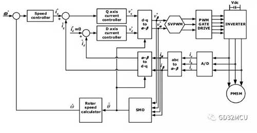
Magnetic field orientation method, sine wave current, sensorless start-up and control;3 resistance current sampling;The inverter circuit is composed of six Power MOSFET.The control block diagram of motor control system is as follows:
Implementation of MTPA
As shown in the system block diagram, the whole system is double closed loop control, with the inner loop being the current control loop and the outer loop being the speed control loop. Set the rotor flux direction to d-axis, and q-axis is the orthogonal axis of d-axis. The control purpose of current loop is to decouple the stator current and flux, and control the stator current to q-axis.
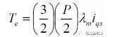
For SPM motors, we set the target control quantity id of the d-axis to 0, and control all the currents on the stator to the q-axis, thus obtaining the Maximum Torque Per Ampere(MTPA). At this time, the torque and speed of PMSM motor are only related to the current component of q-axis, and then we control the current on d-axis through the speed control loop to achieve double closed-loop control.
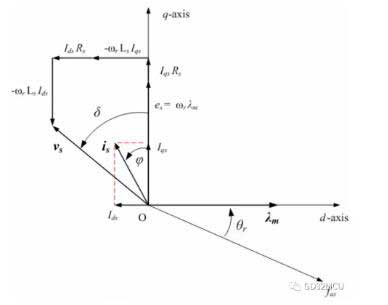
In actual work, because the structure of SPM motor is not ideal, the actual current on d-axis is not zero. At the same time, we will purposefully control the current on the d-axis, so as to realize the motor running beyond the base speed; At this point, we need to add a weak magnetic controller on the d-axis to ensure the realization of MTPA. The vector diagram of SPM motor running is as follows:
Implementation of FOC
There are three-phase currents A, B and C in the actual wiring of PMSM motor. Now, we need to associate the three-phase currents A, B and C with D axis current and Q axis current, and we need to use Clark and Park's two mathematical transformations:
•Clark transformation: (a, b, c)→(α, β), α, β are two orthogonal and static coordinate systems;

•Park transformation: (α, β)→(D, Q), D, Q are two-phase orthogonal rotating coordinate system, where θ is the rotor flux position;
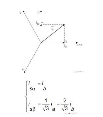
Through Clark and Park's two mathematical changes, we can decompose the three-phase currents of PMSM motor A, B and C into D axis and Q axis, thus realizing field oriented control (FOC). We can also find that the key point of the whole FOC control lies in finding the magnetic flux position θ of the rotor.
Implementation of SVPWM
We can also convert the stator current from D, Q space to α, β space by using the inverse Park transformation. After the magnetic field orientation is completed, the last step of PMSM motor control is to generate the PWM voltage acting on the three-phase terminals of the motor. According to the eight switching states of three-phase inverter, we can list the state table of space vector modulation inverter:
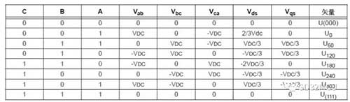
Among them, when the three phases A, B and C are all 0 and 1, they are invalid. We place these two state vectors at the origin of space, and the other six vector states U0→U300 just draw a regular hexagon in space. The traditional 6-step control motor is to add these 6 voltage vectors to the stator of the motor in turn.
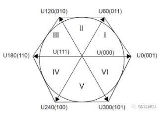
The purpose of space vector modulation (SVPWM) is to form a 360-degree constant amplitude rotating voltage vector in the vector space, so as to reduce the current harmonic component of the inverter output and torque ripple. The realization method of SVPWM is to use two adjacent basic voltage vectors to synthesize the rotating voltage vector Uout in vector space, and the maximum value of Uout is about 0.886*VDC. Take the first quadrant as an example,
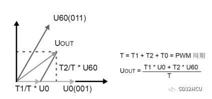
T1 is the acting time of voltage vector U0 in a PWM cycle, T2 is the acting time of voltage vector U60 in a PWM cycle, and T0 is the acting time of zero-order component.
We first determine the sector sector by using the values of V_α and V_β, and then calculate the values of T1, T2 and T0 according to the trigonometric function and Vdc.
A= V_β;
B= 1.7320508*V_α-V_β;
C= -1.7320508*V_α-V_β;
if(A>= 0) {a= 1;} else a= 0;
if(B>= 0) {b= 1;} else b= 0;
if(C>= 0) {c= 1;} else c= 0;
N=a+2*b+4*c;
switch(N)
{
case 1: sector = 2; break;
case 2: sector = 6; break;
case 3: sector = 1; break;
case 4: sector = 4; break;
case 5: sector = 3; break;
case 6: sector = 5; break;
default: break;
}
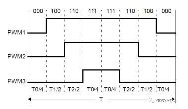
In order to reduce the switching times of MOSFET in inverter circuit, 7-segment space vector synthesis method can be used, which starts and ends with zero vector (000) in each vector sector, with zero vector (111) in the middle and effective vector in the rest of the time. As shown in the figure below:
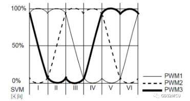
After the SVPWM voltage is applied to the three-phase terminals of PMSM motor, the saddle-shaped phase voltage waveform can be seen, as shown in the following figure:
Realization of rotor angle observer
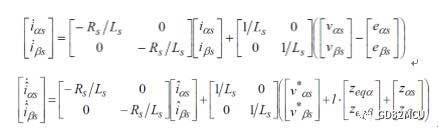
Finding the rotor flux position θ is the key of FOC algorithm. However, in the process of high-speed motor rotation, the Hall sensor is not accurate enough to find the rotor flux position θ accurately. At this time, a rotor angle observer is needed. The angle information of the rotor flux can be obtained from the back EMF. We can't directly measure the back EMF of the motor, but we can use the observer method to calculate the value of the back EMF.
If the sliding mode gain K is large enough, we can find a sliding mode control surface S, so that
The system block diagram of sliding mode observer is as follows:
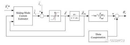
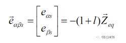
If we want to ensure the stability of sliding mode control surface S, we need to select effective values of K and L to ensure that
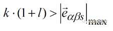
And the value of l must be greater than -1. The final angle θ of the rotor can be calculated by arctangent function.
GD32F130 series MCU can easily realize the SVPWM generator, Park/Clark conversion, PI controller and rotor position observer mentioned above. The built-in high-speed and high-precision SAR ADC and multilevel interrupt system of MCU can ensure the real-time performance of closed-loop control.
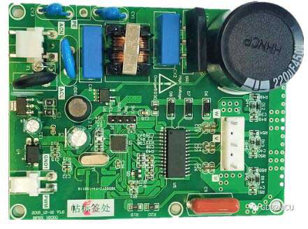
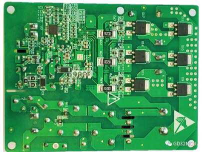
GD32F130 refrigerator frequency conversion board
Frontal picture
Negative picture
Focusing on the 32-bit MCU of the GD32 series of Zhaoyi Innovation (www.bjzycxkjgf.dayinmao.com), the mos FET of SAKO Micro SLKOR (www.slkormicro.com) is widely used in this kind of scheme, such as TVS and ESD tubes which are responsible for motor driving, anti-static and surge discharge in peripheral circuits. Sawei Technology Co., Ltd. (http://www.slkormicro.com) was founded in 2005. For more than ten years, it has been adhering to the concept of "creating value by technology", mainly researching and producing silicon carbide, SiC silicon carbide diode, SiC silicon carbide MOS tube and IGBT single tube. Series 2301, 3401, 3904 and 13n50 products such as high and low voltage MOS tube, ChinaMOS, COOL MOS tube, power management IC, hall Hall element SL1603SL SL1613SH SL1615SH, thyristor, fast recovery diode and diode can also be matched with KingHelm (WWW.BDS666.COM) WiFi antenna, GPS antenna, Beidou antenna and TWS Bluetooth headset ceramic antenna. Mainly used in: new energy vehicles, intelligent robots, inverters, power tools, power electronics, switching power supplies, outdoor lighting power supplies, household appliances, PD fast charging, TWS Bluetooth headsets and other fields.
Note: This article is reproduced from the Internet to support the protection of intellectual property rights. Please indicate the original source and author when reprinting. If there is any infringement, please contact us to delete it.
Company Tel: +86-0755-83044319
Fax/fax:+86-0755-83975897
Email: 1615456225@qq.com
QQ: 3518641314 Manager Li
QQ: 332496225 Manager Qiu
Address: Room 809, Block C, Zhantao Technology Building, No.1079 Minzhi Avenue, Longhua New District, Shenzhen


Site Map | 萨科微 | 金航标 | Slkor | Kinghelm
RU | FR | DE | IT | ES | PT | JA | KO | AR | TR | TH | MS | VI | MG | FA | ZH-TW | HR | BG | SD| GD | SN | SM | PS | LB | KY | KU | HAW | CO | AM | UZ | TG | SU | ST | ML | KK | NY | ZU | YO | TE | TA | SO| PA| NE | MN | MI | LA | LO | KM | KN
| JW | IG | HMN | HA | EO | CEB | BS | BN | UR | HT | KA | EU | AZ | HY | YI |MK | IS | BE | CY | GA | SW | SV | AF | FA | TR | TH | MT | HU | GL | ET | NL | DA | CS | FI | EL | HI | NO | PL | RO | CA | TL | IW | LV | ID | LT | SR | SQ | SL | UK
Copyright ©2015-2025 Shenzhen Slkor Micro Semicon Co., Ltd
