Service hotline
+86 0755-83044319

release time:2022-03-17Author source:SlkorBrowse:10888
foreword
In September, 2020, China defined the goal of carbon neutrality in peak carbon dioxide emissions in 2030 and in 2060. It will be a challenging task for China to achieve zero net emissions in the next 40 years. As far as the motor industry is concerned, motors occupy an important position in the industrial field. According to statistics, the annual power consumption of motors in China accounts for 69% of the total electricity consumption of the whole society, accounting for about 75% of the industrial electricity consumption. Therefore, it is an important task for the motor industry to reduce the carbon emission in the life cycle of the motor and accelerate the process of carbon reduction. Variable frequency speed regulation technology can accurately control the speed of AC motor and make the motor run in an energy-saving state. It is a key measure to reform the speed regulation of traditional motor system and improve the running efficiency of motor system. Traditional frequency converters have the characteristics of large volume, low performance and high price, besides, they also have certain requirements for the environment. For decentralized control occasions, traditional frequency converters are difficult to meet the needs of industrial applications.
In this paper, the control system of VF/ vector inverter based on GD32 MCU adopts modular design, control panel, and user interface can be freely combined according to requirements, which is convenient for installation, programming and initialization design, and easily realizes the speed regulation requirements of asynchronous motor. At the same time, the bus technology can be conveniently connected with the control system and the distributed system, so as to realize the computer-driven system control and the centralized control of the factory workshop. Therefore, the frequency converter has a wide application space in intelligent manufacturing fields such as automobile, food, material conveying and industrial control.
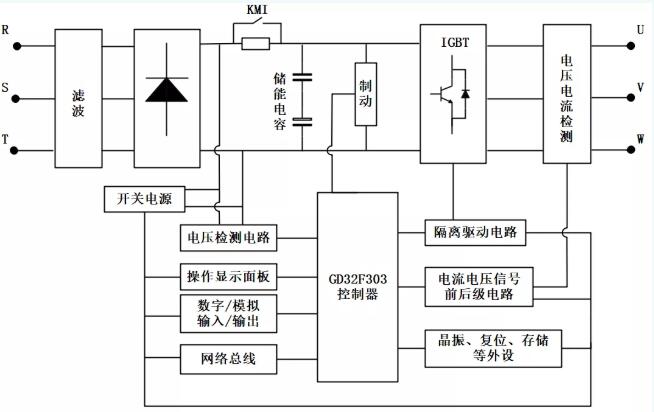
system chart
Program characteristics
GD32F303RCT6 control is adopted in the core scheme, which makes the system have the characteristics of simple structure, convenient implementation, low cost and high reliability. The hardware structure is optimized without reducing the performance of the system, and the hardware system modules are clear and intuitive, which is convenient for installation and use and initialization of programs. Adopting SVPWM control technology in modulation mode can effectively reduce harmonic components of inverter output voltage, with high voltage utilization rate and high control accuracy.
Introduction to GD32F303
Cortex® -M4 core @ 120MHz
Support hardware and software DSP instructions
Flash access is in zero waiting state.
Built-in flash memory from 256 KB to 3072 KB
Built-in SRAM from 48KB to 96kbEXMC interface supports external SDRAM.
Up to 5 uarts (9mbit/s)
Up to 3 SPI's (30mbit/s)
Up to 2 I2C's (400kbit/s)
Up to 2 CAN2.0B
Up to 2 I2S
SDIO support
USB OTG FS support
Up to 3 12-bit, 2.6M SPS ADC (up to 24 channels)
Up to 2 DACs
Standby current is 2uA.
Core principle and implementation of control
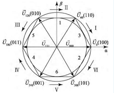
Space vector pulse width modulation (SVPWM) control has the advantages of wide linear range, few higher harmonics and easy digitization, so it is widely used in induction motors. In the traditional three-phase bridge drive circuit, there are eight switch combinations of MOS transistors, namely 000, 001, 010, 011, 100, 101, 110 and 111. Where 000 and 111 are zero vectors. Six non-zero basic voltage space vectors divide the α β plane into six sectors, as shown in the figure. In order to obtain a circular rotating magnetic field, the action time and output sequence of each basic space voltage vector can be synthesized by controlling the action time of eight basic space voltage vectors.
GD32' s TIMER0 module is an enhanced timer module, which is born for motor control. It can generate three groups of 6-channel PWM, and each group of 2-channel PWM is complementary, and can be used to drive H bridge with dead zone. In this paper, the three channels of TIM0 module are used to generate a total of six PWM outputs. The specific steps are as follows:
With the above configuration, the duty ratio can be adjusted in real time with the computing power of GD32F303, and the effect of vector control can be achieved.
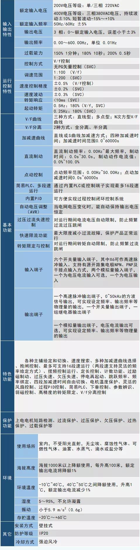
Performance parameters of whole machine
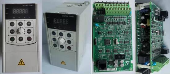
Product display
Disclaimer: This article is reproduced from "GD32MCU". This article only represents the author's personal views, and does not represent the views of Sacco Micro and the industry. It is only for reprinting and sharing to support the protection of intellectual property rights. Please indicate the original source and author when reprinting. If there is any infringement, please contact us to delete it.
Company Tel: +86-0755-83044319
Fax/fax:+86-0755-83975897
Email: 1615456225@qq.com
QQ: 332496225 Manager Qiu
Address: Room 809, Block C, Zhantao Technology Building, No.1079 Minzhi Avenue, Longhua New District, Shenzhen


Site Map | 萨科微 | 金航标 | Slkor | Kinghelm
RU | FR | DE | IT | ES | PT | JA | KO | AR | TR | TH | MS | VI | MG | FA | ZH-TW | HR | BG | SD| GD | SN | SM | PS | LB | KY | KU | HAW | CO | AM | UZ | TG | SU | ST | ML | KK | NY | ZU | YO | TE | TA | SO| PA| NE | MN | MI | LA | LO | KM | KN
| JW | IG | HMN | HA | EO | CEB | BS | BN | UR | HT | KA | EU | AZ | HY | YI |MK | IS | BE | CY | GA | SW | SV | AF | FA | TR | TH | MT | HU | GL | ET | NL | DA | CS | FI | EL | HI | NO | PL | RO | CA | TL | IW | LV | ID | LT | SR | SQ | SL | UK
Copyright ©2015-2025 Shenzhen Slkor Micro Semicon Co., Ltd
