Service hotline
+86 0755-83044319
release time:2022-03-17Author source:SlkorBrowse:10679
There are two kinds of electricity in the world.

��One is alternating current,Its direction is now positive and then negative.

��One is direct current,Its direction never changes.
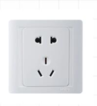
The electricity in our socket at homeIs alternating current.
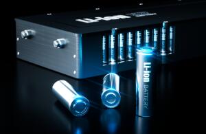
Electricity generated by batteryIs direct current.
Sometimes, we need to convert alternating current into direct current, such as mobile phone charger,

Sometimes, we need to convert direct current into alternating current, such as uninterruptible power supply in data center.

Sometimes, we need to raise or lower the voltage of DC, and there are many boosting circuits in mobile phones.
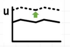
Sometimes, we need to change the frequency and amplitude of alternating current, such as inverter air conditioners and inverter refrigerators.
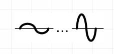
These art of alternating current, alternating current, alternating current, alternating current, alternating current,Is power electronics.On the stage of power electronicsSlay, it's our power device, Tiantuan,They include but are not limited to: diode, MOSFET, IGBT, HEMT, IGCT, GTR…

Their names may or may not be familiar to you.But they have only one function:Turn on, or turn off the current.

Yes, it's an electronic switch.It's no different from the switch on the wall of our house.Some power devices have two terminals, such as diodes.
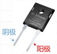
Packaged diode
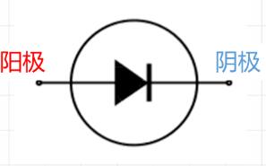
Circuit symbol of diode
It's a one-way lane.
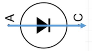
Current flows from anode to cathode.The flow is unimpeded.
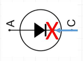
Flow from cathode to anodeIs that this road is blocked.Because the diode has only two terminals, its turn-on and turn-off can't be controlled by itself. When the current comes, it has to be collected, and it can't stay when it goes.And some power devices have three terminals. They are controllable power devices, and no matter how much current they face, they can say I don't want them loudly.And the absolute ability of controllable power devices in the celestial sphere,It's IGBT.IGBT is a super electronic switch, which can withstand ultra-high voltage.The AC voltage in the socket of our home is 220V, while the IGBT chip as thin as paper can withstand up to 6500V. Generally, the maximum current of all household appliances in our home will not exceed 30A, while an IGBT chip the size of a fingernail can flow about 200A of current!The following figure shows four IGBT chips and four diode chips mounted on the substrate.
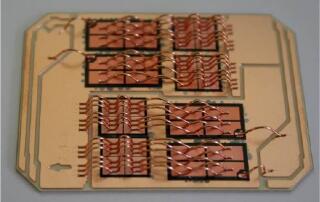
However, a bare chip like this cannot be used directly. We need to repackage the chip into a shell, which is filled with insulating materials, and lead the electrodes of the chip to the external terminals, thus forming a usable IGBT product.
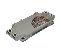
Some cases have only one IGBT chip in the case, while others may have dozens or twenty chips. Thus, various IGBT single tubes and modules are formed. The maximum current of IGBT in single tube package is about 100A, and the maximum rated current of IGBT module can reach 3600A!
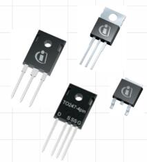
monotube
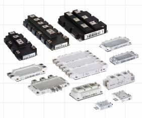
module
The IGBT in the circuit diagram is generally represented by the following figure, and G represents the gate gate, which is used to receive commands. C represents collector collector, e represents emitter emitter, and collector and emitter are used to conduct current. Usually, IGBT is off, and once the gate receives an on command, the current will continuously flow from the collector to the emitter.
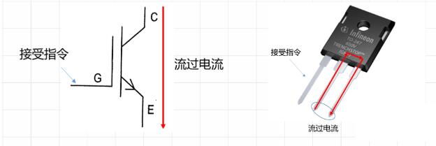
Just like the switch on the wall of your home, press it, the switch closes, and the electric light lights up; Click again, and the light goes out.

Of course, operating IGBT is no longer a hand, but an electronic pulse.When the high level comes, the device is turned on; When the low level comes, the device turns off.

The manual switch may be operated once or twice a second, while our electronic switch can be opened and closed tens of thousands or hundreds of thousands of times a second!This is that electronic switch we nee,That is, the power device.When several power devices are combined together, they can make their debut. The name of these combinations is "topology". Every topology has its own unique skills.Topology consisting of 4 or 6 diodes, which can convert alternating current into direct current;
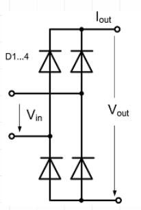
Single-phase rectifier bridge
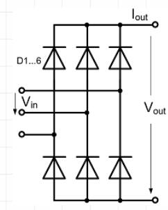
Three-phase rectifier bridge
A topology consisting of 4 or 6 IGBT's or MOSFET's can convert DC into AC;
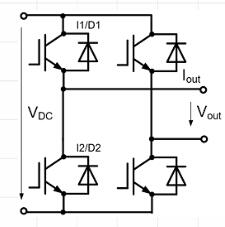
Full bridge inverter circuit
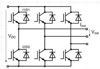
Three-phase bridge inverter circuit
And the topology of IGBT diode plus other passive components can increase or decrease the DC voltage.
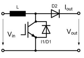
boost-up circuit
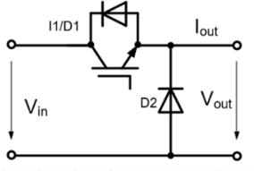
Step-down circuit
The topology seems a bit complicated? Never mind, we can design some logo for them.
����
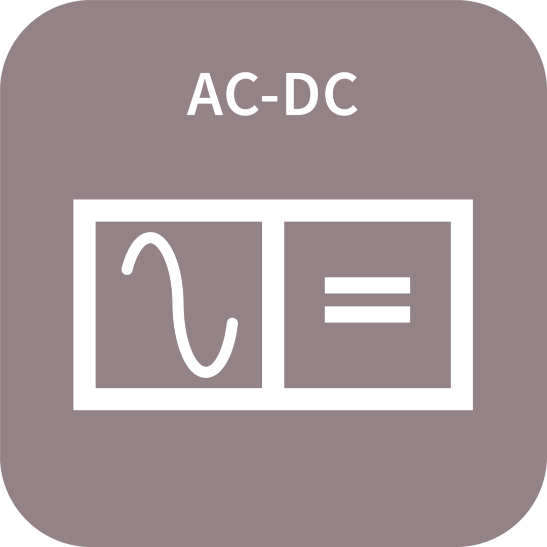
rectifying circuit
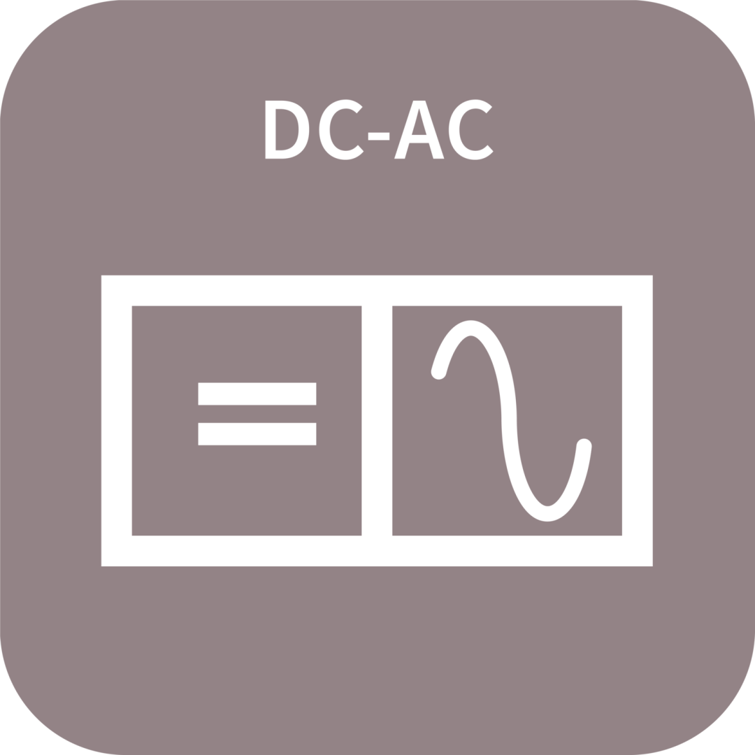
Inverter circuit
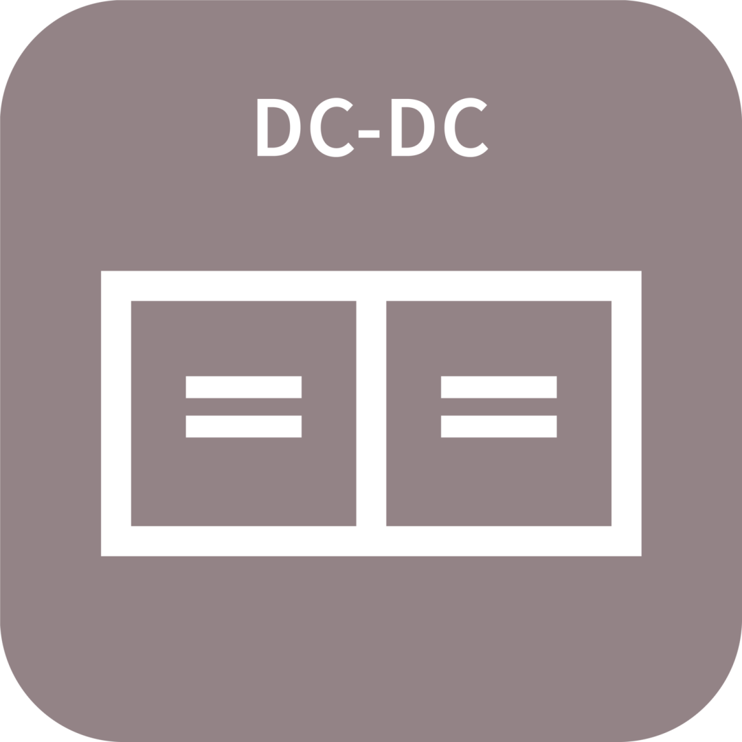
Boost/buck circuit
No matter how complex or huge the electrical equipment is, it is made up of these basic topologies and components.Many times, in the same device, the electric energy will be transformed more than once, such as the charging pile of electric vehicle.
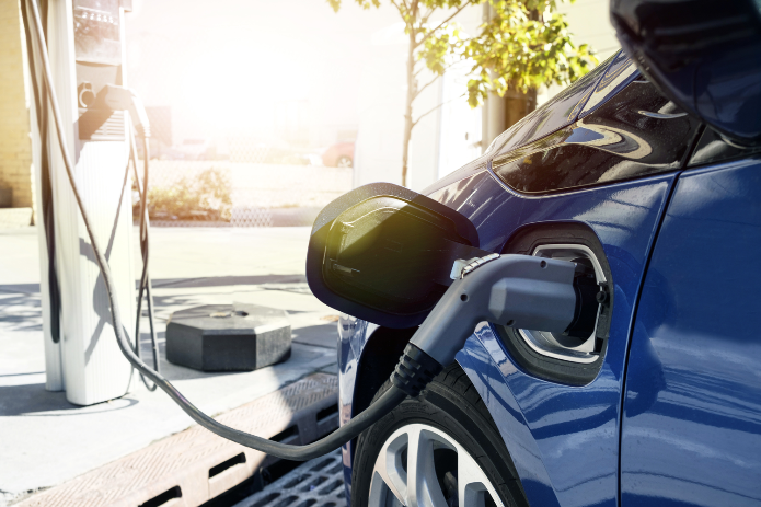
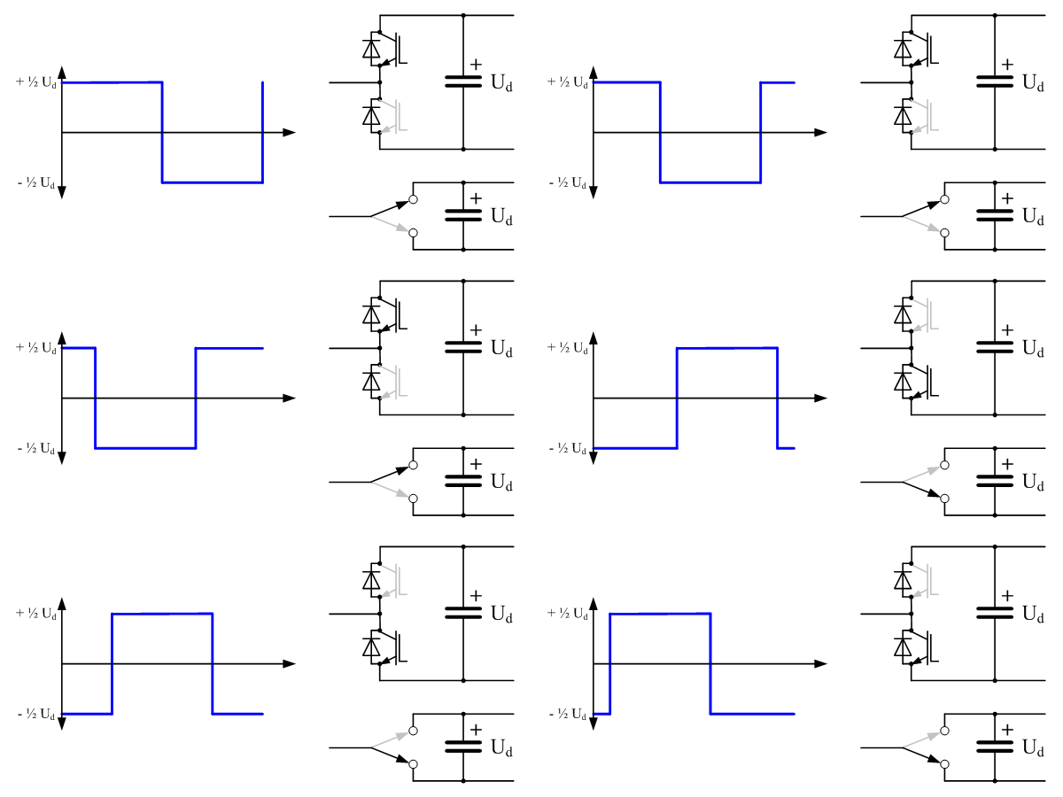
The output voltage of mobile phone charger is generally 5V, but do you know how high the battery voltage of electric car is? Up to 750V!The battery can only be charged by direct current, while 380V alternating current flows in the three-phase industrial power grid (different from 220V alternating current in the household power grid). So how does the charging pile change 380V alternating current into 750V direct current?First, 380V AC will pass through a rectifying circuit and become about 500V DC. At this time, the direct current voltage is not high enough, and secondly, the voltage cannot be adjusted, so it cannot be directly supplied to the battery for charging.The rectified DC current enters an inverter circuit, which is the topology composed of IGBT or MOSFET that we introduced before. Or IGBT MOSFET switches at high speed under the control of gate signal, and changes DC into AC with extremely high frequency. This alternating current is a square wave. By adjusting the proportion of high level, you can freely adjust the equivalent voltage.
High-frequency alternating current enters a rectifying circuit, and finally becomes the output voltage of 250V~750V to charge the car.The topology of the whole electric energy conversion is as follows:
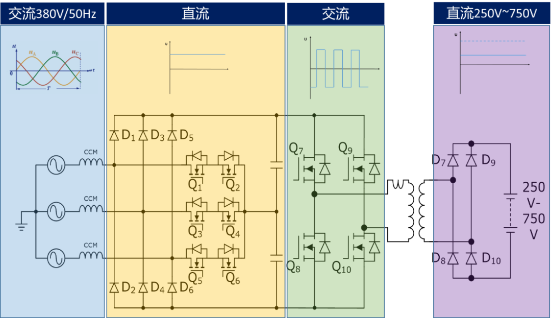
It's a bit complicated to look at, but it's simple to change to a logo, that is, rectifier circuit+inverter circuit+rectifier circuit, like this:

Look, the power electronic system is as simple as building blocks to put all the functions together. Now you can also build your own system!
Disclaimer: This article is reproduced from "Infineon Industrial Semiconductor". This article only represents the author's personal views, and does not represent the views of Sacco Micro and the industry. It is only for reprinting and sharing to support the protection of intellectual property rights. Please indicate the original source and author when reprinting. If there is any infringement, please contact us to delete it.
Company Tel: +86-0755-83044319
Fax/fax:+86-0755-83975897
Email: 1615456225@qq.com
QQ: 3518641314 Manager Li
QQ: 332496225 Manager Qiu
Address: Room 809, Block C, Zhantao Technology Building, No.1079 Minzhi Avenue, Longhua New District, Shenzhen


Site Map | 萨科微 | 金航标 | Slkor | Kinghelm
RU | FR | DE | IT | ES | PT | JA | KO | AR | TR | TH | MS | VI | MG | FA | ZH-TW | HR | BG | SD| GD | SN | SM | PS | LB | KY | KU | HAW | CO | AM | UZ | TG | SU | ST | ML | KK | NY | ZU | YO | TE | TA | SO| PA| NE | MN | MI | LA | LO | KM | KN
| JW | IG | HMN | HA | EO | CEB | BS | BN | UR | HT | KA | EU | AZ | HY | YI |MK | IS | BE | CY | GA | SW | SV | AF | FA | TR | TH | MT | HU | GL | ET | NL | DA | CS | FI | EL | HI | NO | PL | RO | CA | TL | IW | LV | ID | LT | SR | SQ | SL | UK
Copyright ©2015-2025 Shenzhen Slkor Micro Semicon Co., Ltd