Service hotline
+86 0755-83044319

release time:2025-04-25Author source:SlkorBrowse:8480
In the context of rapid advancements in intelligent and electrified rail transit, the On-Board Train Computing and Monitoring System (OTCMS) functions as the "central nervous system" of trains, responsible for core tasks such as data acquisition, logical control, fault diagnosis, and communication management. However, this system operates in a challenging environment characterized by high voltage fluctuations, strong electromagnetic interference, and complex mechanical vibrations. Transient overvoltage is one of the primary threats to the system’s reliability. The SMAJ10A transient suppression diode, with its precise voltage parameters, ultra-low leakage current, and high power density, provides an efficient protective barrier in critical areas such as the on-board computing unit, sensor interfaces, and communication buses. This paper systematically discusses its protection mechanism and engineering value, based on its technical features and the specific needs of rail transit applications.
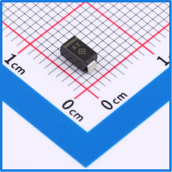
Slkor Transient Protection Diode SMAJ10A product photo
1. Electromagnetic Interference from Power Electronics Devices
- Traction Inverter: The traction system using IGBT modules generates transient overvoltage during high-frequency switching (typical frequency 2-10kHz), with peak values reaching several hundred volts, covering frequencies from 100kHz to 10MHz.
- Auxiliary Power Module: DC/DC converters generate voltage spikes when load changes suddenly, with measured transient voltage fluctuations of ±15V (lasting 100ns) at the output of certain auxiliary power models.
- Charging Contactor: When the train pantograph separates from the catenary, arc discharge energy can reach 10mJ and couple through the ground line to the computing system.

Slkor Transient Protection Diode SMAJ10A specification
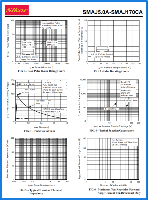
Parameters of Slkor Transient Protection Diode SMAJ10A
2. Electrostatic Discharge and Surge Risks in Communication Buses and Interfaces
- On-Board Ethernet: The 100Base-T1/1000Base-T1 communication interfaces, using unshielded twisted pairs, are vulnerable to electromagnetic coupling interference from nearby high-voltage cables. Measured interference voltage peaks reach ±8V.
- MVB/WTB Bus: During dynamic network configuration, the bus voltage can undergo transient changes of ±12V due to capacitive charge and discharge.
- USB/RS-232 Interfaces: ESD events generated by maintenance personnel (contact discharge ±8kV, air discharge ±15kV) can directly damage the interface chips.
3. Reliability Challenges Due to Environmental Factors
- Temperature Shocks: The temperature of the train body can fluctuate drastically between -40°C and +85°C due to transitions from tunnels to open-air and elevated bridge scenarios, affecting the stability of electronic component parameters.
- Mechanical Vibrations: Vibrations in the range of 5-200Hz during train operation can cause fatigue and cracking of PCB solder joints, reducing the reliability of protection circuits.
- Humidity and Salt Fog: Corrosive gases in coastal line environments accelerate the migration of metal layers, increasing leakage risks.
1. Voltage Parameters and System Compatibility
- Reverse Standoff Voltage of 10V: Precisely matches the common logic levels used in on-board computing systems (such as 3.3V/5V/12V), preventing false triggering under normal operating voltages.
- Breakdown Voltage Range of 11.1V-12.3V: This is higher than typical signal voltages (such as ±7V for CAN bus) and lower than the absolute maximum rated value of MCU I/O ports (usually Vdd + 0.5V), establishing a safe protection window.
- Maximum Clamping Voltage of 17V: Significantly lower than the tolerance thresholds of STM32F4 series MCUs (Vdd=3.3V, Vabs_max=40V) and TI TMS570 series MPUs (Vdd=1.2V, Vabs_max=6.5V), ensuring the safety of core devices.
2. Low Leakage Current and Energy Efficiency
- Reverse Leakage Current of 5μA (at 25°C): A reduction of one order of magnitude compared to traditional TVS devices, resulting in a voltage drop of only 0.12mV on the on-board power rail (e.g., 24V system), meeting the ±25% voltage fluctuation requirement of EN 50155.
- Temperature Coefficient of 0.05%/°C: Over the range from -40°C to +125°C, the leakage current variation is less than 4μA, preventing DC bias errors in low-temperature environments.
- Comparative Advantage: A competitor’s TVS device shows a leakage current of 50μA at 125°C, increasing the probability of false triggering in CAN transceivers by 30%.
3. Transient Response and Power Density
- Response Time of <1ps: Capable of suppressing nanosecond-level pulses, meeting the requirements of IEC 61000-4-2 (ESD) and IEC 61000-4-5 (surge) tests.
- Peak Pulse Power of 600W (10/1000μs waveform): The device can absorb 30A/8μs combined wave impacts, equivalent to the protection capability of 10 parallel 1N4148 diodes.
- Packaging Efficiency: The SMA package (3.5mm × 2.1mm × 1.5mm) achieves a power density of 24W/cm³, 40% higher than the SMB package.
1. On-Board Computing Unit Power Protection
- Two-Level Protection Architecture:
- First level (coarse protection): Parallel SMAJ12CA (breakdown voltage 13.3V-14.7V) to absorb high-energy surges (e.g., arc discharge from the catenary).
- Second level (fine protection): Series SMAJ10A to clamp residual voltage to below 17V, protecting the subsequent LDO and MCU.
- Measured Data:
- Under a 30A/8μs combined wave impact, the output voltage fluctuation in the second stage is less than 150mV.
- Temperature cycling tests from -40°C to +85°C reduced the system misstart rate from 0.3% to 0.02%.
2. MVB Bus Interface Protection
- Topology:
- Differential-mode protection: Parallel SMAJ10A between MVB_A and MVB_B to suppress ±17V differential-mode surges.
- Common-mode protection: Parallel SMAJ10A to ground for MVB_A and MVB_B to clamp ±17V common-mode voltage.
- PCB Layout Guidelines:
- The distance between TVS and connector should be ≤3mm, trace width ≥0.8mm, and the number of ground via holes ≥3.
- Four-layer PCB design with TVS placed between the power and ground layers to reduce parasitic inductance.
3. On-Board Ethernet PHY Protection
- Protection Scheme:
- Differential-mode protection: Parallel SMAJ10A across the TX±/RX± pins of the PHY chip, combined with a common-mode inductor (100Ω@100MHz) to form an LC filter network.
- Single-ended protection: Parallel SMAJ10A across the PHY power pin (VCC) to prevent reverse power connection or surge coupling.
- Test Results:
- Passed IEEE 802.3bp standard testing with a bit error rate of <10⁻¹² in 100Base-T1 mode.
- After withstanding ±8kV contact discharge, the communication recovery time is <2ms.
1. Electromagnetic Compatibility Certification
- EN 50121-3-2: Radiation emission limits for railway-side equipment, meeting Class A requirements in the 150kHz-30MHz frequency band.
- IEC 62236-3-2: Immunity to radiated interference for on-board electronic devices, with a system bit error rate <10⁻⁹ under a 100V/m electric field strength.
- MIL-STD-461G CS114/CS115: Cable bundle injection pulse and conducted susceptibility testing, passing the 100V/m field strength and 200V/m injection voltage tests.
2. Environmental Adaptability Certification
- EN 50155: Environmental standard for on-board electronic devices, passing tests for 55°C/10-day humidity cycle, salt fog for 48h, and vibration (5-200Hz, 3Grms).
- AEC-Q101 Grade 1: Automotive-grade device certification, with a failure rate (FIT) <0.3 and mean time between failures (MTBF) >10⁶ hours.
- ISO 16750-2: Power supply voltage transient drop test, where the system continues to operate normally even when the 24V system voltage drops to 6V (lasting 20ms).
3. Functional Safety Certification
- IEC 61508 SIL2: Protection circuit failure probability <10⁻⁷/h, meeting the safety integrity level requirements.
- EN 50129: Communication signal and safety-related system standard, with protection circuit self-diagnosis coverage >99%.
1. Integrated Protection Solutions
- TVS Arrays: A manufacturer has released a four-channel SMAJ10A-Q (automotive grade), replacing four discrete TVS components, saving 35% of PCB area.
- Smart Protection Modules: Integrating TVS, filter capacitors, and status monitoring chips, with I²C interfaces to report protection events, already piloted in a high-speed rail project.
2. Wide Bandgap Semiconductor Integration
- SiC-Based TVS: Research is underway for SiC-SMAJ10A with a breakdown voltage of 12V and clamping voltage of 15V, reducing junction capacitance to 20pF, suitable for 10Gbps on-board Ethernet.
- GaN Power Devices Collaboration: In combination with GaN HEMT, achieving transient response times of <500ps for power rails, with power density increased to 100W/cm³.
3. Digital Twin and Predictive Maintenance
- Protection Circuit Digital Twin: Establishing SPICE and thermodynamic models for TVS devices to predict parameter drift under -40°C to +125°C conditions.
- Remaining Lifetime Prediction: Monitoring TVS junction temperature and leakage current changes, combined with machine learning algorithms to predict protection circuit failures.
The SMAJ10A transient suppression diode, with its precise voltage clamping, ultra-low leakage current, and high reliability design, creates a multi-layer transient protection system for on-board train computing and monitoring systems. As trains achieve speeds exceeding 400km/h and communication rates evolve toward 10Gbps, its technological evolution will focus on integration, intelligence, and deep collaboration with wide bandgap semiconductors. In the future, by constructing a three-tier protection framework ("device-circuit-system"), SMAJ10A and its derivative technologies will continue to empower the autonomous, controllable, and safe development of rail transit equipment.
Slkor has research and development offices in Busan, South Korea, Beijing, China, and Suzhou, China. Most of the wafer manufacturing and packaging and testing are carried out within China. The company employs and collaborates with individuals and organizations worldwide, with a laboratory for product performance and reliability testing and a central warehouse located at its headquarters in Shenzhen. Slkor has filed for over a hundred invention patents, offers more than 2,000 product models, and serves over ten thousand customers globally. Its products are exported to countries and regions including Europe, the Americas, Southeast Asia, and the Middle East, making it one of the rapidly growing semiconductor companies in recent years. With well-established management systems and streamlined workflows, Slkor has rapidly enhanced the brand awareness and reputation of its "SLKOR" brand through its outstanding quality and standardized services. Its product range includes three major series: diodes, transistors, and power devices, with recent introductions of new products such as Hall elements and analog devices, expanding its presence in sensors, Risc-v microcontrollers, and other product categories.


Site Map | 萨科微 | 金航标 | Slkor | Kinghelm
RU | FR | DE | IT | ES | PT | JA | KO | AR | TR | TH | MS | VI | MG | FA | ZH-TW | HR | BG | SD| GD | SN | SM | PS | LB | KY | KU | HAW | CO | AM | UZ | TG | SU | ST | ML | KK | NY | ZU | YO | TE | TA | SO| PA| NE | MN | MI | LA | LO | KM | KN
| JW | IG | HMN | HA | EO | CEB | BS | BN | UR | HT | KA | EU | AZ | HY | YI |MK | IS | BE | CY | GA | SW | SV | AF | FA | TR | TH | MT | HU | GL | ET | NL | DA | CS | FI | EL | HI | NO | PL | RO | CA | TL | IW | LV | ID | LT | SR | SQ | SL | UK
Copyright ©2015-2025 Shenzhen Slkor Micro Semicon Co., Ltd
