Service hotline
+86 0755-83044319
release time:2022-03-17Author source:SlkorBrowse:10453
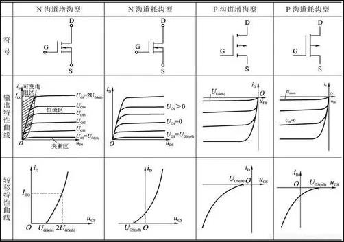
MOS is similar to triode, but triode is a current-driven type, while MOS is a voltage-driven type, so the G terminal voltage of MOS needs to be considered when controlling. The general N-channel MOS can be turned on at 3V, but in order to consider reliability, a resistor is often added and connected to about 12V, which is commonly used. As shown in a picture in our product, it is a motor drive, which uses the switching characteristics of MOS. In addition, the transistor and MOS used in the digital circuit is a switch, because the digital circuit has only 0 and 1. The PWM in the picture is directly from the IO port of the microcontroller, and 0V and 5V are variable. Behind a push-pull circuit, and then to MOS.

How to use MOS tube as switch circuit
In the figure, the positive power of the battery is connected to the 2-pin source of the field effect transistor Q1 through the switch S1. Since Q1 is a P-channel tube, its 1-pin gate provides a positive potential voltage through the R20 resistor, so it cannot be powered on and the voltage cannot be Continue to pass, the 3v voltage regulator IC input pin can't get voltage, so it can't work and can't boot! At this time, if we press the SW1 power-on button, the positive electricity is applied to the base of the transistor Q2 through the button, R11, R23, D4, the base of the transistor Q2 gets a positive potential, and the transistor is turned on (when the transistor was mentioned earlier As already mentioned), since the emitter of the transistor is directly grounded, the conduction of the transistor Q2 is equivalent to the direct grounding of the gate of Q1, and the voltage applied to it through the R20 resistor is directly connected to the ground, and the gate of Q1 goes from high to high. The potential becomes low, and when Q1 is turned on, it is added to the input pin of the 3v voltage regulator IC from Q1. The 3v voltage regulator IC is the one that U1 outputs the 3v working voltage vcc and supplies it to the master control. The master control resets it to 0 and reads Take a series of actions such as firmware program detection, input a control voltage to PWR_ON, and then send it to the base of Q2 through R24 and R13, keep Q2 in a conducting state, even if you release the power button to disconnect the base of Q1 At this time, the control voltage sent by the main control is maintained, and Q2 can always be in a conducting state, and Q1 can continuously provide working voltage to the 3v voltage regulator IC! SW1 also sends control signals with different time and times to the main control PLAYON pin through the voltage divider of the two resistors R11 and R30 at the same time. control points to achieve different working states!


Site Map | 萨科微 | 金航标 | Slkor | Kinghelm
RU | FR | DE | IT | ES | PT | JA | KO | AR | TR | TH | MS | VI | MG | FA | ZH-TW | HR | BG | SD| GD | SN | SM | PS | LB | KY | KU | HAW | CO | AM | UZ | TG | SU | ST | ML | KK | NY | ZU | YO | TE | TA | SO| PA| NE | MN | MI | LA | LO | KM | KN
| JW | IG | HMN | HA | EO | CEB | BS | BN | UR | HT | KA | EU | AZ | HY | YI |MK | IS | BE | CY | GA | SW | SV | AF | FA | TR | TH | MT | HU | GL | ET | NL | DA | CS | FI | EL | HI | NO | PL | RO | CA | TL | IW | LV | ID | LT | SR | SQ | SL | UK
Copyright ©2015-2025 Shenzhen Slkor Micro Semicon Co., Ltd