Service hotline
+86 0755-83044319

release time:2022-03-17Author source:SlkorBrowse:11580
Low frequency comes from two parts: differential mode and common mode filtering.
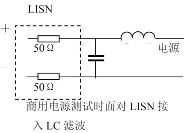
Differential mode filtering tries to reduce the noise on the power line of the current return line.
This mean that noise on that power line exist in the shell and the return line. Therefore, the purpose of filtering is to shunt it to the loop before it leaves the shell, so as to ensure that it returns and cannot be measured. Set an inductor on the power line to block it from going out, and provide a capacitor between the power supply and the return line to provide a low-impedance channel with noise. Usually, LISN (Line Impedance Stabilization Network) is used in commercial testing. The tested power supply is connected to LISN through an inductor and a capacitor, providing 50 ω source impedance.
Sometimes the noise may be so small that inductance is not needed. Capacitor and 50 ω resistor form a voltage divider path which is enough to transfer most of the noise. In order for this circuit to work, the ESR of the capacitor has to be limited. Try multilayer capacitors and metallized plastic capacitors.
Select numeric value
Differential mode filtering is shown in the following circuit:
It consists of a second-order LC circuit. According to the measurement, we know the noise spectrum before filtering, and at the same time, we know that the second-order filter to be designed attenuates the noise at 40 dB/Dec. This is the starting point that determines the turning point of the filter.
First, find the lowest frequency differential mode component. E.g. 20dB at 100kHz. Then that star frequency is 100kHz/ 10 =30kHz (because of the square root of two poles).
Now draw a straight line at the top of the noise (30kHz) with a slope of 40dB/Dec If there are no other peak points, the resonant frequency of the filter is 30kHz. To select LC parameters. There are many choices of LC parameters, the price of inductor is more expensive than that of capacitor, and the choice should weigh the price and loss.
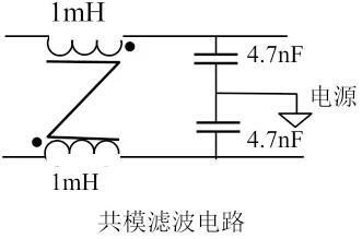
Common mode filtering
Common mode filter is easier to design than differential mode filter, because there are few types to choose.
A common mode filter:Common-mode capacitance (called Y capacitance in business; X is differential mode capacitance)+a common mode choke.
As shown in the figure below:
The common-mode capacitor shunts the line to the ground, while the common mode choke provides the balanced impedance-that is, it provides the same impedance for the source and the return line, and presents a high impedance path for the common-mode noise. For differential mode inductance, it is zero.
Numerical selection
Contrary to the common-mode differential-mode selection element, the capacitor here is more expensive than the inductor.There are two reasons:
1.Capacitor grounding, must be able to withstand instantaneous 3kV even 6kV Voltage, so it is very bulky. There is also a strict safety limit on the value of the current flowing, which limits the maximum value that the common-mode capacitor can be applied to, typically several nanofarads.
therefore,You choose the maximum allowable capacitance, and apply the same technology as previously determined. LC, use the same steps to determine the inductance value. Don't panic if you calculate a large common mode choke value. The two coils of common mode choke flow the same current, but there seems to be no net current. Many turns without saturation.
2.When calculating the required inductance, two common-mode capacitors are connected in parallel (the value is doubled), and two coils of common mode choke are connected in series.
therefore,Get 2 times turns and 4 times inductance. This gives you an extra 8 times noise suppression. The capacitance is equal to 9.4nF, while the inductance is 4mH, and its cut-off frequency is 26kHz.
Capacitance and limitation
There is a corresponding frequency limitation of capacitance, which limits its application in EMI filtering. Electrolytic capacitor has a considerable ESR, which means that it is regarded as resistive above RC frequency and is no longer a pole.
For example, capacitance = 100 μ f ESR = 100 mω, which becomes resistive at a frequency of 16kHz. It is no longer used for EMI control.
Actually, ceramic or plastic capacitors are often used for EMI filtering.
They are also limited due to the lead inductance.
The 1 μF capacitor is only effective below 1MHz.
Above 1MHz, it can reach 10MHz with 100nF capacitor.
To suppress noise, 1 μF, 100nF and 10nF can be used in parallel.
There is also a limitation on inductance (its coil resistance, though not good for power loss, has no obvious influence on noise suppression).
The most important limitation is the distributed capacitance, which may be connected in parallel with the inductor. Above a certain frequency, the capacitive reactance is lower than the inductive reactance, and above this frequency, the inductance no longer blocks the noise.
Example: suppose 1mH has a capacitance of 100pF. Then its inductive impedance stops increasing above about 500kHz, and actually decreases. Of course, the smaller the inductance, the smaller the distributed capacitance and the higher the cutoff frequency.
Two inductors can be connected in series instead of one large inductor, because two inductors are connected in series to increase the inductance and their capacitors are connected in series to reduce the capacitance, but this is never done in practice.Varistor has capacitance. Many designers need a varistor to absorb the transient voltage of power grid.The varistor has a small capacitance and can be used as a part of filtering, which has unexpected gains.Note: Add the varistor between the source and the return line to the ground. The varistor also has leakage current, so the Y capacitance should be reduced accordingly.
Two inductors with one magnetic core: common-mode and differential-mode inductors, saving cost and volume.However, the design should pay attention to: winding a common mode choke, for example, 47 turns on one side, while winding the other side of the source line by one more turn.This inductor is still a common mode choke, but now there is a series inductor with an inductance of (48 2 -47 2 )A L, which is much larger than that of winding one turn on such a magnetic core. However, the composite magnetic field in the magnetic core is not zero, so you should check that the magnetic core should not be saturated at the maximum current.
Is 100dB attenuation available?
Low-frequency filters only use two-pole filters, so it is not necessary to add one more capacitor, one more inductor, or one more inductor and capacitor for high-order filtering, because such filters are difficult to design;
For commercial design, high-order filtering requires another inductor, which means that production is difficult. Except in special circumstances, there is no need for such a filter. The four-pole attenuation is very fast, and it may be worse if six poles are needed.If it is calculated that an inductor needs to be attenuated by 60~80dB in the low frequency region, it is best to go back and study the circuit wiring.
Possible method: increase switching frequency to reduce filtering requirements. There are performance limitations of components, and there are leakage and cross interference between vias in the actual PCB layout.Between the bottom line and the top line, an attenuation of 100dB can be obtained.A commercial filter can also be bought, because it makes greater attenuation by itself.Because major commercial devices have paid attention to avoiding cross interference of circuit layout, and have sealed the filter in a metal shell.Of course, you can do it yourself, but the cost is higher.
Disclaimer: This article is reproduced from "Power Core City". This article only represents the author's personal views, and does not represent the views of Sacco Micro and the industry. It is only for reprinting and sharing to support the protection of intellectual property rights. Please indicate the original source and author when reprinting. If there is any infringement, please contact us to delete it.
Company Tel: +86-0755-83044319
Fax/fax:+86-0755-83975897
Email: 1615456225@qq.com
QQ: 332496225 Manager Qiu
Address: Room 809, Block C, Zhantao Technology Building, No.1079 Minzhi Avenue, Longhua New District, Shenzhen


Site Map | 萨科微 | 金航标 | Slkor | Kinghelm
RU | FR | DE | IT | ES | PT | JA | KO | AR | TR | TH | MS | VI | MG | FA | ZH-TW | HR | BG | SD| GD | SN | SM | PS | LB | KY | KU | HAW | CO | AM | UZ | TG | SU | ST | ML | KK | NY | ZU | YO | TE | TA | SO| PA| NE | MN | MI | LA | LO | KM | KN
| JW | IG | HMN | HA | EO | CEB | BS | BN | UR | HT | KA | EU | AZ | HY | YI |MK | IS | BE | CY | GA | SW | SV | AF | FA | TR | TH | MT | HU | GL | ET | NL | DA | CS | FI | EL | HI | NO | PL | RO | CA | TL | IW | LV | ID | LT | SR | SQ | SL | UK
Copyright ©2015-2025 Shenzhen Slkor Micro Semicon Co., Ltd
