Service hotline
+86 0755-83044319

release time:2022-03-17Author source:SlkorBrowse:11640
Electronic components often fail in use. Failure means that the circuit may fail, thus affecting the normal operation of the equipment. The failure reasons and common faults of common components are analyzed here.
Most of the failures of electronic equipment are ultimately caused by the failure of electronic components. If you are familiar with the failure causes of components and locate the failure causes of components in time, you can eliminate the failures in time and make the equipment run normally.
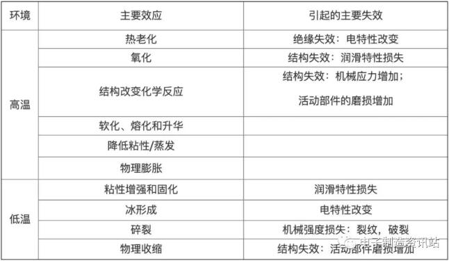
Temperature failure
One of the important factors of component failure is the influence of ambient temperature on components.
Influence of temperature change on semiconductor devices
As the forward voltage drop of P-N junction is greatly affected by temperature, the voltage transmission characteristics and anti-interference degree of bipolar semiconductor logic elements (TTL, HTL and other integrated circuits) with P-N as basic units are also closely related to temperature.
When the temperature rises, the forward voltage drop of the P-N junction decreases, and the opening and closing levels of the P-N junction decrease, which makes the low-level anti-interference voltage tolerance of the element decrease with the temperature rising. The tolerance of high-level anti-interference voltage increases with the increase of temperature, resulting in output level deviation, waveform distortion, steady-state imbalance, and even thermal breakdown.
P-N pair, the basic unit of bipolar semiconductor device, is very sensitive to the change of temperature. When the P-N junction is reversely biased, the reverse leakage current formed by minority carriers is affected by the change of temperature, and its relationship is as follows: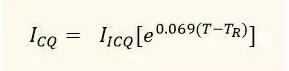
In the formula:
ICQ: Reverse leakage current at temperature T0C
IICQ: reverse leakage current at temperature TR℃
T-TR: absolute value of temperature change
It can be seen from the above formula that the ICQ will double every time the temperature rises by 10℃. This will cause the working point of transistor amplifier to drift, the transistor current amplification factor to change, the characteristic curve to change, and the dynamic range to become smaller.
The relationship between temperature and allowable power consumption is as follows:
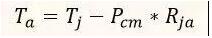
In the formula:
Pcm: maximum allowable power consumption
Ta: Operating ambient temperature
Tj: junction temperature of transistor
Rja: Thermal resistance between junction and environment
It can be seen from the above equation that the maximum allowable power consumption of the transistor will decrease with the increase of temperature.
Influence of temperature change on resistance
The influence of resistance temperature change is mainly when the temperature rises. The increase of temperature will lead to the increase of resistance thermal noise, the deviation of resistance from the nominal value and the decrease of allowable dissipation probability. For example, when the temperature of RXT series carbon film resistance rises to 100℃, the allowable dissipation probability is only 20% of the nominal value.
This characteristic of resistance is not only bad. For example, specially designed resistors: PTC (Positive Temperature Coefficient Thermistor) and NTC (negative temperature coefficient), whose resistance values are greatly affected by temperature, can be used as sensors. For PTC, when its temperature rises to a certain threshold, its resistance value will increase sharply.
With this feature, it can be used in the overcurrent protection circuit of circuit board-when the current through it increases to its threshold current due to some kind of fault, the temperature of PTC rises sharply, and at the same time, its resistance value becomes larger, limiting the current through it, so as to protect the circuit. After troubleshooting, the current through PTC decreases, the temperature of PTC returns to normal, and its resistance value also returns to its normal value. For NTC, its characteristic is that its resistance decreases with the increase of temperature.
Influence of temperature change on capacitance
The change of temperature will cause the change of dielectric loss of capacitor, thus affecting its service life. When the temperature rises by 10℃, the service life of the capacitor decreases by 50%, and at the same time, the resistance-capacitance time constant changes, and even thermal breakdown occurs due to excessive dielectric loss.
Humidity leads to failure.
One of the important factors of component failure is the influence of environmental humidity on components. When the humidity is too high, when the dust containing acidity and alkalinity falls on the circuit board, it will corrode the solder joints and wiring of components, causing the solder joints to fall off and the joints to break.Excessive humidity is also the main cause of leakage coupling. However, low humidity is easy to generate static electricity, so the humidity of the environment should be controlled at a reasonable level.
Excessive voltage leads to failure.
One of the important factors of component failure is the influence of high voltage on components. An important condition to ensure the normal operation of components is that the voltage applied to components should be stable. Excessive voltage will increase the heat loss of components, and heavy voltage will cause electrical breakdown of components. Take the capacitor, its failure rate is proportional to the fifth power of the voltage applied across the capacitor. For the integrated circuit, the voltage exceeding its maximum allowable voltage will cause direct damage to the device.
Voltage breakdown means that all electronic devices have the highest withstand voltage, beyond which there is a risk of failure. The failure forms of active components and passive components are slightly different, but they all have allowable upper limits of voltage. Transistors have withstand voltage values, and exceeding the withstand voltage values will damage the components. For example, exceeding the withstand voltage values of diodes, capacitors and other components will lead to their breakdown. If the energy is too high, the components will be scrapped.
Vibration and impact cause failure.
One of the important factors of component failure is the influence of vibration and impact on components. Mechanical vibration and impact will accelerate the failure of some internal defective components, resulting in catastrophic failure. Mechanical vibration will also loosen solder joints and line pressing points, resulting in poor contact. If the vibration leads to the unnecessary contact of wires, some unexpected consequences will be produced.
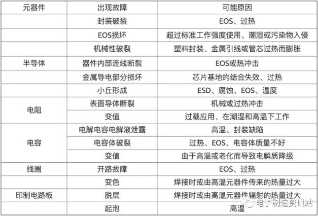
Possible failure modes and failure analysis:
Resistance failure analysis
The failure mechanism of resistors and potentiometers varies with different types. The main failure modes of non-linear resistors and potentiometers are open circuit, resistance drift, mechanical damage of leads and contact damage. The main failure modes of wound resistors and potentiometers are open circuit, mechanical damage of leads and contact damage.
There are mainly the following four categories:
Carbon film resistor.Lead breakage, matrix defects, poor film uniformity, film notch defects, poor contact between film material and lead end, film and matrix pollution, etc.
Metal film resistor.Uneven resistance film, rupture of resistance film, unstable lead, decomposition of resistance film, silver migration, reduction of resistance film oxide, electrostatic charge, rupture of lead, corona discharge, etc.
Wire wound resistor.Poor contact, current corrosion, weak leads, poor insulation of wires, melting of solder joints, etc.
Variable resistor.Poor contact, poor welding, broken contact or lead off, impurity pollution, poor epoxy glue, shaft tilt, etc. Resistors are prone to deterioration and open circuit faults. After the resistance is deteriorated, it often drifts when the resistance becomes larger. Generally, resistors are not repaired, but directly replaced with new resistors. Winding resistance When the resistance wire is burnt out, in some cases, the burnt-out treatment can be re-welded before use.
Resistance deterioration is mostly caused by poor heat dissipation, excessive humidity or manufacturing defects, while burnout is caused by abnormal circuits, such as short circuit and overload.
There are two common phenomena of resistor burn-out. One is that excessive current makes the resistor heat up, which causes the resistor burn-out. At this time, the surface of the resistor is burnt, which is easy to find. In the other case, due to the instantaneous high voltage applied to the resistor, the resistor is open or the resistance value becomes larger. In this case, the surface of the resistor is generally not obviously changed, and this kind of faulty resistor can often be found in high-voltage circuits.
Variable resistors or potentiometers are mainly wired or non-wired. Their common failure modes are: parameter drift, open circuit, short circuit, poor contact, loud dynamic noise, mechanical damage, etc. However, the actual data show that the main failure modes are quite different between laboratory test and field use, with the majority of laboratory failures being parameter drift, while the majority of field failures being poor contact and open circuit.
The fault of poor contact of potentiometer is common in field use. For example, it accounts for 90% in telecom equipment and 87% in TV sets, so poor contact is a fatal weak link for potentiometers.
The main reasons for poor contact are as follows:
The contact pressure is too small, the stress is relaxed, the sliding contact deviates from the track or the conductive layer, the mechanical assembly is improper, or the contact deformation is caused by a large mechanical load (such as collision, drop, etc.).
The conductive layer or contact track forms various nonconductive films at the contact due to oxidation and pollution.
The conductive layer or resistance alloy wire is worn or burned, resulting in poor contact of sliding point.
Open circuit failure of potentiometer is mainly caused by local overheating or mechanical damage.For example, the potentiometer's conductive layer or resistance alloy wire is oxidized, corroded, polluted, or overloaded due to improper process (such as uneven winding and uneven thickness of conductive film layer, etc.), resulting in local overheating, which burns out the potentiometer and opens the circuit; If the sliding contact surface is not smooth and the contact pressure is too high, the winding will be severely worn and disconnected, resulting in open circuit; Improper selection and use of potentiometer, or failure of electronic equipment endangers potentiometer, making it work under overload or heavy load. These will accelerate the damage of potentiometer.
Capacitance failure analysis
Common failures of capacitors mainly include breakdown, open circuit, degradation of electrical parameters, electrolyte leakage and mechanical damage. The main causes of these failures are as follows:
puncture
There are defects, defects, impurities or conductive ions in the medium; Material aging; Electrochemical breakdown of dielectric; In the environment of high humidity or low air pressure, the inter-electrode edge arcing; Instantaneous short circuit of dielectric under mechanical stress; Metal ions migrate to form conductive channel or edge flashover discharge; The breakdown of air gap inside the material causes dielectric breakdown; Mechanical damage in the medium manufacturing process; The change of the molecular structure of the medium and the applied voltage higher than the rated value, etc.
open a way
Breakdown causes insulation of electrodes and leads; Electrolytic capacitor anode lead foil is corroded and broken (or mechanically broken); The contact point between the lead wire and the electrode forms an oxide layer, resulting in a low-level open circuit; Poor contact or insulation between the lead wire and the electrode; The metal foil drawn from the anode of electrolytic capacitor is open due to corrosion; Working electrolyte dries up or freezes; Instantaneous open circuit between electrolyte and dielectric under mechanical stress.
Electrical parameter degradation
Aging and thermal decomposition of wet dielectric; Metal ion migration of the electrode; The existence and change of residual stress; Surface pollution; Self-healing effect of metallized electrode; Evaporation and thickening of working electrolyte; Electrolytic corrosion or chemical corrosion of the electrode occurs; And that contact resistance of the lead electrode is increase; And the influence of impurities and harmful ions.
Because the actual capacitor works under the combined action of working stress and environmental stress, one or several failure modes and mechanisms will be produced, and one failure mode will lead to another failure mode or mechanism.
For example, temperature stress can not only promote surface oxidation, accelerate the influence of aging, accelerate the degradation of electrical parameters, but also promote the decrease of electric field strength and accelerate the early arrival of dielectric breakdown. Moreover, the influence degree of these stresses is a function of time.
Therefore, the failure mechanism of capacitors is closely related to the types of products, the types of materials, the differences of structures, the manufacturing process and environmental conditions, working stress and other factors.
It's easy to find the breakdown fault of capacitor, but it's difficult to determine the specific fault component when multiple components are connected in parallel. The determination of capacitor open circuit fault can be realized by connecting capacitors of the same type and capacity in parallel with the detected capacitors, and observing whether the circuit functions recover. It is troublesome to check the change of electrical parameters. Generally, the following methods can be used.
First, one of the leads of the capacitor should be ironed off the circuit board to avoid the influence of the surrounding components. Secondly, according to the different conditions of capacitors, different methods are used for inspection.
Detection of electrolytic capacitor
Place the multimeter in the electrical block, and the measuring range depends on the capacity and withstand voltage of the electrolytic capacitor to be measured. The measuring range of electrolytic capacitor with small capacity and high withstand voltage should be located in R× 10kW gear; The measuring range of electrolytic capacitor with large capacity and low withstand voltage should be located in R× 1kW gear. Observe the charging current, the discharging time (the speed at which the hands return) and the resistance value indicated by the hands at last.
The quality identification methods of electrolytic capacitors are as follows:
① The charging current is large, the rising speed of the hands is fast, the discharging time is long, and the returning speed of the hands is slow, indicating that the capacity is sufficient.
② The charging current is small, the rising speed of the watch hands is slow, the discharging time is short, and the returning speed of the watch hands is fast, indicating that the capacity is small and the quality is poor.
③ The charging current is zero, and the hands do not move, indicating that the electrolytic capacitor has failed.
(4) At the end of discharge, the resistance indicated when the hands are returned to the end is large, indicating good insulation performance and small leakage.
⑤ At the end of discharge, the resistance value indicated when the hands are returned to the end is small, indicating poor insulation performance and serious leakage.
General capacitor inspection with capacity above 1mF. The multimeter can be electrically blocked (R× 10kW) The same polarity multiple measurement method is used to check the leakage degree and whether it is broken down. Touch the two probes of the multimeter with the two leads of the measured capacitor, and observe whether the probes swing slightly. For capacitors with large capacity, the hands swing obviously; For capacitors with small capacity, the swing of the hands is not obvious. Then touch the lead of the capacitor with the probe again, three times and four times (the probe is out of alignment), and observe whether the needle swings slightly every time. If the hand swings every time you touch it from the second time, it means that the capacitor has leakage. If the hands don't move after several times of touching, the capacitor is good. If the hands reach the end point at the first touch, the capacitor has been broken down. In addition, some digital multimeters can measure capacitors with a capacity of 1mF~20mF.
Check the capacitor with capacity below 1mF. The actual value of the capacitor can be measured accurately by using the capacitance measuring block of the digital multimeter. If there is no digital multimeter with capacitance measurement function, it can only be checked for breakdown and short circuit with ohmic resistor. Connect a good capacitor of the same capacity in parallel with the suspected capacitor, and check whether it is open.
Accurate measurement of capacitor parameters.The LCR bridge can be used to accurately measure the capacity of a single capacitor, and the transistor characteristic tester can be used to measure the withstand voltage.
And failure analysis of inductors and transformers.
Such components include inductors, transformers, oscillating coils, filter coils, etc. The faults are mostly caused by external reasons, for example, when the load is short-circuited, the current flowing through the coil exceeds the rated value, and the transformer temperature rises, resulting in coil short circuit, open circuit or insulation breakdown. When the ventilation is poor, the temperature is too high or it is damp, the phenomenon of electric leakage or insulation breakdown will also occur.
There are the following common phenomena and causes of transformer failures: when the transformer is powered on, if the iron core makes a buzzing noise, the cause of the failure may be that the iron core is not clamped or the transformer is overloaded; If it is hot, smoky, burnt or the fuse is blown, the coil may be short-circuited or overloaded.
Generally, the following methods are adopted for fault inspection of inductance and transformer components:
Direct current resistance measurement method.Measure the quality of inductance components with the resistance of multimeter. When measuring antenna coil and oscillating coil, the measuring range should be placed at the minimum electrical resistance (such as R× 1W block); When measuring the cycle and the input and output of the transformer, the measuring range should be set at low blocking (R× 10W or R× 100W block), the measured resistance value is compared with the maintenance data or daily accumulated experience data, and if it is very close, it means that the tested component is normal; If the resistance value is much smaller than the empirical data, it indicates that the coil has a local short circuit; If the indicating value of the hand is zero, the coil is short-circuited.
It should be noted that the secondary resistance of the oscillating coil, antenna coil and the middle ring is very small, only a few tenths of an ohm, so be careful when reading, and don't mistake it for short circuit. With high blocking (R× 10kW) When measuring the resistance between the primary coil and the secondary coil, it should be infinite. If there is a certain resistance value between the primary and secondary, it means that there is leakage between the primary and secondary.
Power-on inspection.The power transformer can be checked by electrifying to see if the secondary voltage drops. If the secondary voltage drops, it is suspected that the secondary (or primary) has a local short circuit. When the transformer quickly burns or smells burnt or smokes after being energized, it can be judged that there must be a local short circuit in the transformer.
Instrumental inspection method.The high frequency Q meter can be used to measure the inductance and its Q value, and the inductor short circuit meter can also be used to judge the local short circuit of the low frequency coil. The insulation resistance between primary and secondary of power transformer can be measured by megohmmeter. If the leakage phenomenon of the transformer is found, it may be caused by poor insulation or dampness. At this time, the transformer can be removed to remove moisture and dry. In addition, all kinds of carbon brushes or copper brushes of voltage-regulating transformers are easily worn out under improper maintenance and use, and their fragments and carbon deposits often burn down the transformer due to the burning of the coil in the short-circuit part, so attention should be paid to maintenance at ordinary times.
Disclaimer: This article is reproduced from "Electronic Manufacturing Consulting Station". This article only represents the author's personal views, and does not represent the views of Sacco Micro and the industry. It is only for reprinting and sharing to support the protection of intellectual property rights. Please indicate the original source and author when reprinting. If there is any infringement, please contact us to delete it.
Company Tel: +86-0755-83044319
Fax/fax:+86-0755-83975897
Email: 1615456225@qq.com
QQ: 3518641314 Manager Li
QQ: 332496225 Manager Qiu
Address: Room 809, Block C, Zhantao Technology Building, No.1079 Minzhi Avenue, Longhua New District, Shenzhen


Site Map | 萨科微 | 金航标 | Slkor | Kinghelm
RU | FR | DE | IT | ES | PT | JA | KO | AR | TR | TH | MS | VI | MG | FA | ZH-TW | HR | BG | SD| GD | SN | SM | PS | LB | KY | KU | HAW | CO | AM | UZ | TG | SU | ST | ML | KK | NY | ZU | YO | TE | TA | SO| PA| NE | MN | MI | LA | LO | KM | KN
| JW | IG | HMN | HA | EO | CEB | BS | BN | UR | HT | KA | EU | AZ | HY | YI |MK | IS | BE | CY | GA | SW | SV | AF | FA | TR | TH | MT | HU | GL | ET | NL | DA | CS | FI | EL | HI | NO | PL | RO | CA | TL | IW | LV | ID | LT | SR | SQ | SL | UK
Copyright ©2015-2025 Shenzhen Slkor Micro Semicon Co., Ltd
