Service hotline
+86 0755-83044319

release time:2022-03-17Author source:SlkorBrowse:10046
Why do you always put two capacitors of 0.1uF and 0.01uF in the circuit?
And bypass and decoupling.
The two concepts of Bypass Capacitor and Decoupling Capacitor are common in circuits, but it is not easy to really understand them. Articles explaining capacitors: Animation explaining the working principle of capacitors, you can click for reference.
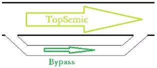
To understand these two words, we have to go back to the English context.Bypass means to cut a path in English, and it also means this in the circuit, as shown in the figure below.
Couple means a pair in English, which is extended to the meaning of pairing and coupling. If the signal in system A causes the signal in system B, then it is said that there is a Coupling phenomenon between system A and system B, as shown in the following figure. Decoupling means to weaken this coupling.
Bypass and decoupling in circuit
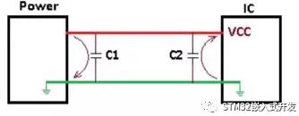
As shown in the figure below, DC Power supplies power to the chip IC, and two capacitors are incorporated into the circuit. Related article recommendation: Why should a 0.1uF capacitor be placed near the MCU chip?
bypass
If the Power is interfered, it is usually an interference signal with high frequency, which may make the IC unable to work normally. Connect a capacitor C1 in parallel near Power, because the capacitor is open to DC and has low resistance to AC. The interference signal with higher frequency flows back to the ground through C1, and the interference signal that would have passed through IC flows to GND through capacitor shortcut. C1 here is the function of bypass capacitor.
decouple
As the working frequency of integrated circuits is generally high, when the IC is started or the working frequency is switched, a large current fluctuation will be generated on the Power supply conductor, and this interference signal will be directly fed back to the Power, which will make it fluctuate. Connect a capacitor C2 in parallel near the VCC Power supply port of the IC. Because the capacitor has the function of energy storage, it can provide instantaneous current to the IC and reduce the influence of IC current fluctuation interference on power. C2 here acts as a decoupling capacitor.
Why use two capacitors?
Back to the question mentioned at the beginning of this article, why use two capacitors of 0.1uF and 0.01uF?
The calculation formulas of capacitance and capacitive reactance are as follows:
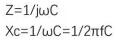
Capacitance is inversely proportional to frequency and capacitance. The larger the capacitance and the higher the frequency, the smaller the capacitive reactance. It can be simply understood that the larger the capacitance, the better the filtering effect. Then, with the 0.1uF capacitor bypass, isn't it a waste to add another 0.01uF capacitor?
Actually, for a specific capacitor, it is capacitive when the signal frequency is lower than its self-resonant frequency, and inductive when the signal frequency is higher than its self-resonant frequency. When two capacitors of 0.1uF and 0.01uF are connected in parallel, the filtering frequency range is widened.
Disclaimer: This article is reproduced from "Single Chip Microcomputer and Embedded". This article only represents the author's personal views, and does not represent the views of Sacco Micro and the industry. It is only for reprinting and sharing to support the protection of intellectual property rights. Please indicate the original source and author when reprinting. If there is any infringement, please contact us to delete it.
Company Tel: +86-0755-83044319
Fax/fax:+86-0755-83975897
Email: 1615456225@qq.com
QQ: 3518641314 Manager Li
QQ: 332496225 Manager Qiu
Address: Room 809, Block C, Zhantao Technology Building, No.1079 Minzhi Avenue, Longhua New District, Shenzhen


Site Map | 萨科微 | 金航标 | Slkor | Kinghelm
RU | FR | DE | IT | ES | PT | JA | KO | AR | TR | TH | MS | VI | MG | FA | ZH-TW | HR | BG | SD| GD | SN | SM | PS | LB | KY | KU | HAW | CO | AM | UZ | TG | SU | ST | ML | KK | NY | ZU | YO | TE | TA | SO| PA| NE | MN | MI | LA | LO | KM | KN
| JW | IG | HMN | HA | EO | CEB | BS | BN | UR | HT | KA | EU | AZ | HY | YI |MK | IS | BE | CY | GA | SW | SV | AF | FA | TR | TH | MT | HU | GL | ET | NL | DA | CS | FI | EL | HI | NO | PL | RO | CA | TL | IW | LV | ID | LT | SR | SQ | SL | UK
Copyright ©2015-2025 Shenzhen Slkor Micro Semicon Co., Ltd
