Service hotline
+86 0755-83044319

release time:2025-06-25Author source:SlkorBrowse:5842
With the rapid development of portable electronic devices, battery life has become one of the key metrics for evaluating product performance. Low power circuit design for batteries is at the core of enhancing battery life and extending device usage time. In the design practices of many engineers, a critical issue that needs to be solved is how to completely shut off current when the device is turned off, to prevent unnecessary battery drain. Today, Sun Gaofei, an engineer at Slkor Semiconductor, will provide an in-depth analysis of the key points and implementation plan for battery low power circuit design.
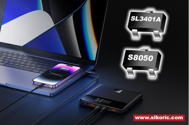
In low power circuit design for batteries, the design of the power-on circuit is the first step to ensure the device operates properly. A common design solution is to cleverly use a Slkor SL3401A PMOS and a Slkor S8050 NPN transistor. When the power button SW is pressed, the logic of the entire circuit changes. At this moment, the base of the Slkor S8050 NPN transistor (Q1) receives an appropriate bias voltage, which turns Q1 on. The conduction of Q1 acts like an open gate, allowing the battery power to be successfully connected to the circuit. The main control chip starts receiving power and enters its operational state. At the same time, the POWER ON control pin of the main control chip outputs a high-level signal, which locks the power supply circuit in the on-state. Even after releasing the power button SW, the device continues to operate steadily, as the power supply circuit remains locked. This design not only enables the convenience of a one-button power-on operation but also ensures stable power supply after the device is turned on, laying the foundation for subsequent operations.
When the device needs to be powered off, precise circuit design is also required to achieve low power consumption. Upon pressing and holding the SW button again, the main control chip, with its internal detection mechanism, can quickly capture the shutdown signal. At this point, the main control chip controls the POWER ON pin to stop output, switching the high-level signal to a low-level signal. This change in output from the POWER ON pin directly affects the operation of the Slkor S8050 NPN transistor (Q1). Without the bias voltage, Q1 turns off, causing the Slkor SL3401A PMOS to cut off, thus shutting the gate of the circuit and disconnecting the battery from the device circuit. As a result, the device is powered off. This method ensures that after the device is powered off, no current flows through the entire circuit, achieving the goal of 0 power consumption and effectively preventing unnecessary battery drain when the device is idle.
In practical use, devices inevitably need charging, and the circuit design during the charging process is also critical for low power management. In special cases, when an external charger is connected to the device, a VBUS high-level signal is generated. This high-level signal forces the charging circuit to open, overriding the normal circuit logic. Upon detecting the VBUS high-level signal, the main control chip quickly switches to charging mode and begins charging the battery. When the charger is disconnected, the VBUS high-level signal disappears, and the circuit automatically responds by disconnecting the power supply circuit to prevent unnecessary current consumption in a non-charging state, further ensuring low power operation.
As a professional semiconductor manufacturer, Slkor Semiconductor is committed to providing cost-effective semiconductor components to engineers and companies. From basic components like PMOS and NPN transistors to high-performance main control chips, Slkor offers solutions for diverse design needs. Additionally, they provide comprehensive application design guidance. In the process of low power circuit design for batteries, Slkor Semiconductor's technical team provides full technical support, including circuit design, component selection, and debugging, according to the specific needs and application scenarios of clients. This support helps customers solve various design challenges and ensures the efficiency and reliability of the design solution.
In conclusion, battery low power circuit application design requires meticulous planning and layout across various stages, including power-on, power-off, and charging. By skillfully using semiconductor components and logically planning the circuit, it is possible to achieve low power operation of the device and the ideal state of 0 power consumption after shutdown. With high-quality products and professional technical support, Slkor Semiconductor provides a strong guarantee for low power circuit design, assisting engineers in creating more competitive portable electronic devices.


Site Map | 萨科微 | 金航标 | Slkor | Kinghelm
RU | FR | DE | IT | ES | PT | JA | KO | AR | TR | TH | MS | VI | MG | FA | ZH-TW | HR | BG | SD| GD | SN | SM | PS | LB | KY | KU | HAW | CO | AM | UZ | TG | SU | ST | ML | KK | NY | ZU | YO | TE | TA | SO| PA| NE | MN | MI | LA | LO | KM | KN
| JW | IG | HMN | HA | EO | CEB | BS | BN | UR | HT | KA | EU | AZ | HY | YI |MK | IS | BE | CY | GA | SW | SV | AF | FA | TR | TH | MT | HU | GL | ET | NL | DA | CS | FI | EL | HI | NO | PL | RO | CA | TL | IW | LV | ID | LT | SR | SQ | SL | UK
Copyright ©2015-2025 Shenzhen Slkor Micro Semicon Co., Ltd
