Service hotline
+86 0755-83044319
release time:2022-03-17Author source:SlkorBrowse:11914

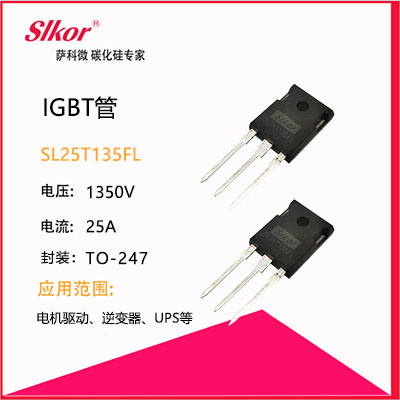
IGBT, also known as Insulated Gate Bipolar Transistor, is a composite fully-controlled voltage-driven power semiconductor device composed of a Bipolar Transistor (BJT) and an Insulated Gate Field Effect Transistor (MOS). Its input is a MOSFET and its output is a PNP transistor. Therefore, it can be regarded as a Darlington transistor with metal oxide semiconductor input.
It combines the advantages of high input impedance of MOSFET and low on-voltage drop of GTR, and has the characteristics of easy driving, large peak current capacity, self-shutdown, and high switching frequency (10-40hz). It has gradually replaced thyristor and gate turn-off thyristor (GTO), and is currently the fastest growing new generation of power electronic devices. Widely used in small volume and high efficiency variable frequency power supply, motor speed regulation, uninterruptible power supply and inverter welding machine.
The working principle of IGBT
The IGBT is controlled by gate G, emitter E and collector c. If the voltage between the gate and the emitter of the IGBT, that is, the driving voltage, is too low, the IGBT cannot work stably; if the withstand voltage between the gate and the emitter is too high or even exceeds, the IGBT may be permanently damaged.
Likewise, if the voltage between the collector and emitter of the IGBT exceeds the allowable value, the current flowing through the IGBT will exceed the limit, causing the junction temperature of the IGBT to exceed the allowable value, at which point the IGBT may be permanently damaged.
IGBT polarity judgment
When testing IGBTs, an analog multimeter should be selected. First set the multimeter at r1k, and use the multimeter to measure the resistance between the two poles. If the resistance value of one pole and other poles is infinite, the resistance value of this pole and other poles is still infinite after changing the probe, this is the grid g, use a multimeter to measure the resistance between the other poles. If the measured resistance is infinite, the resistance becomes smaller after replacing the probe. When the measured resistance is small, the red probe touches the collector C and the black probe touches the emitter e
Judgment of IGBT Quality
When judging the quality of the IGBT, you must choose an analog multimeter (the internal battery voltage of the electronic multimeter is too low), or you can use a 9V battery instead. First, set the multimeter to r10k (when using r1k, the internal voltage is too low to turn on the IGBT). Use a black stylus to connect the collector C of the IGBT and the red test pen to the emitter E of the IGBT, and the pointer of the multimeter is zero.
Touch the grid G and the collector C at the same time with your finger to trigger the IGBT to turn on, and the multimeter pointer swings obviously to the direction with smaller resistance, which can be kept in a certain position. Then touch both gate G and emitter E with your finger. At this time, the IGBT is blocked, and the pointer of the multimeter is returning to zero during the detection. The above phenomena are consistent, and it can be judged that the IGBT is good, otherwise there is a problem with the IGBT.


Site Map | 萨科微 | 金航标 | Slkor | Kinghelm
RU | FR | DE | IT | ES | PT | JA | KO | AR | TR | TH | MS | VI | MG | FA | ZH-TW | HR | BG | SD| GD | SN | SM | PS | LB | KY | KU | HAW | CO | AM | UZ | TG | SU | ST | ML | KK | NY | ZU | YO | TE | TA | SO| PA| NE | MN | MI | LA | LO | KM | KN
| JW | IG | HMN | HA | EO | CEB | BS | BN | UR | HT | KA | EU | AZ | HY | YI |MK | IS | BE | CY | GA | SW | SV | AF | FA | TR | TH | MT | HU | GL | ET | NL | DA | CS | FI | EL | HI | NO | PL | RO | CA | TL | IW | LV | ID | LT | SR | SQ | SL | UK
Copyright ©2015-2025 Shenzhen Slkor Micro Semicon Co., Ltd